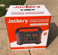
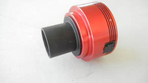
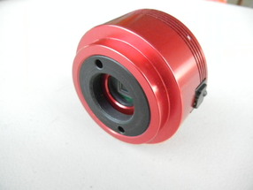
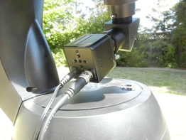
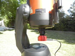
 I have been powering my astronomy rig in the field using either two 100Ah lead acid deep cycle batteries or my Yamaha EF2000is generator for a dozen years. While relatively cheap, batteries are heavy (50-60lbs), can only be discharged to 50% of capacity, are not voltage regulated, need to be maintained monthly, and do not have built in meters, USB charging, AC output, etc. At $1000 a generator is expensive, heavy (~50lbs), does not have either DC or USB outputs and is not permitted at most star parties. So I decided it was time to look at Li based power with solar recharging. Why Li? Because the power to weight ratio is much, much better than lead acid batteries, Li batteries have a higher depth of discharge (DoD) than lead acid batteries without damage and they maintain their voltage through most of the discharge cycle. The obvious downside to Li based power is the higher initial cost. 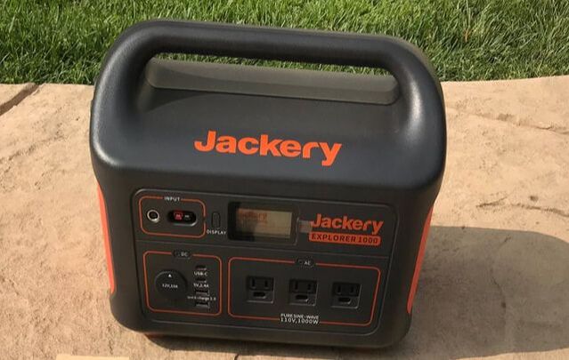 Solar Generators At first I considered 100Ahr LiFePO4 batteries like the well regarded Battleborn batteries marketed primarily to the RV and boating industries since I am planning to use these to add solar to my new RV in the coming year. But after much research I decided that a "solar generator" rather than a standalone Li battery is a much better match for astronomy applications. What is a solar generator? It is a Li battery with a battery management system (BMS), DC, AC and USB outputs, power input/output/SOC meter, an LCD display, power charging ports and a solar charge controller all built into a single lightweight, rugged and portable unit. There are many different suppliers of solar generators available today which are primarily marketed to the outdoor adventurer. Many solar generators use Lithium Nickel Manganese Cobalt Oxide (NMC) chemistry instead of LiFePO4 because of its nearly 2 to 1 advantage in energy density to weight ratio. I zeroed in on the solar generators from Jackery after reading many positive reviews about their design, features and performance. Their line of solar generators includes 160Whr (13.9Ah @ 12V), 240Whr (20Ah @ 12V), 300Whr(25Ah @ 12V), 500Whr (41.7Ah @ 12V) and 1000Whr(83.5Ah @ 12V) models with prices ranging from $139.99 to $999.99 with frequent sale pricing. These provide plenty of options for different astronomy needs. I contacted Jackery and suggested that amateur astronomers might be a market for them and they were kind enough one of their 1000Whr generators with a pair of their 100w solar panels for me to put to the test with my astronomy rig. Below are the results of more than a month of extensive testing in my backyard observatory and on a 3 night star gazing adventure in the field. 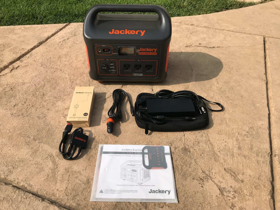 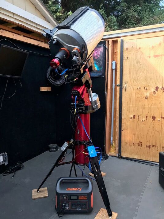 The Jackery comes well packaged with the generator shipped triple boxed. The PS1000 generator includes an AC charger in a soft carrying case, a car charger cable, an adapter to connect two solar panels in parallel for faster charging and a user manual. It enjoys free shipping, a 30 day free return and a 2 year warranty. Inside the box I found a registration card which enables a warranty extension to 3 years. The generator is solidly built using rigid ABS plastic casing and sports a smart functional design. With dimensions of 13.1 x 9.2 x 11.1 in. (L x W x D) it is only slightly larger than my lead acid batteries and fits nicely between the tripod legs of my mount. It's molded handle and weight of only 22lbs makes it a breeze to transport. Everything one needs to access is conveniently located on the front of the generator including: 1) a 10A DC cigarette adapter socket with dust cap; 2) a 5V 2.4A USB-A output ; 3) two 3A USB-C outputs; 4) a USB-A Quick Charge 3.0 output; 5) three 110V AC outputs from the internal 1000w pure sine wave inverter; 6) 8mm and Anderson Power Pole inputs to recharge the generator; 7) an LCD display which shows power output, input and battery % SOC and is low enough intensity as to not disturb fellow astronomers. 8) On/Off buttons for the power outputs and the display. A small LED light is mounted on the side. The Jackery can be recharged with the included AC charger, with optional solar panels or by car. Observatory Testing I conducted a series of tests of the Jackery using my Software Bisque MyT mount, Celestron C11 OTA, Celestron focuser, ASI1600MC camera, Orion SSAG guide camera (not shown in the accompanying photo), Astrozap dew heat strap, TEMP-est cooling fans, and a Pegasus Power Box Advanced (PPBA). I used a cigarette adapter to 5.5mm x 2.1mm cable to supply power from the Jackery to the PPBA which in turn distributed power to the MyT, dew heater and focuser. The cameras and fans drew their power from the MyT. Since the MyT requires 48V I used a DC-DC up converter on the output of the PPBA to transform 12V to 48V rather than using the less efficient AC adapter. I use The Sky X (TSX) to control everything except the PPBA which is controlled by its own application. I did run one test using the Jackery's AC outlet to power the MyT without any problems but that method unnecessarily wastes power in the conversion process. Since the first month of testing occurred during the massive wildfires here in CA I could not actually image. Instead, I ran everything exactly as I would during a regular imaging session with the ASI capturing dark frames to the laptop, the fans running, the guider taking dark frames and the heater powered at 50%. Since a laptop is typically the most power hungry device used and not everyone uses the same laptop, if they use one at all, I decided to run 3 different test setups: 1. Everything but the 15.4" laptop powered by the Jackery through the PPBA. 2. As in 1 but with the laptop powered through the Jackery's AC inverter. 3 As in 1 including a BeeLink mini-pc powered by the Jackery through the PPBA. The Beelink ran TSX and I used my laptop on its internal battery linked to the Beelink via Team Viewer as a monitor only to minimize power consumption. For these tests I tried not to discharge the generator batteries below 20% SOC to be very conservative in terms of long term battery lifetime. The manufacturer specs the batteries to > 500 full discharges to 0% SOC so you could increase all of my total times below by 25% if you are comfortable using the full capacity of the Jackery. Here are the test results: Test #1: I was able to achieve a total run time of 27hrs over 3 successive sessions before reaching a SOC of 20%. That is enough power for 3 nights of 9 hour imaging sessions without the need for a recharge in between, although a recharge is always possible. I noted that the ouput voltage of the Jackery remained steady at 12.9-13.1V all the way down to 20% SOC. Test # 2: To extend the session as long as possible, I disconnected the laptop from the Jackery when it reached a SOC of 25% and let the laptop run on its own internal battery until it reached ~5% and the Jackery reached 20%. This powered everything for 9hrs, sufficient for a long overnight imaging session powering everything with the Jackery. Considering that the Jackery was able to be fully recharged with 2 solar panels in 7.5hr , one could run indefinitely this way so long as a reasonable degree of sunshine is available during the day. Alternatively, the Jackery could be recharged in 6-7hrs with an AC outlet. Test#3: For this test I only used my laptop on its internal battery to check in on the BeeLink via Team Viewer occasionally. As I show below, the BeeLink which has no monitor consumes much less power than a 15.4" laptop so I was able to run for 8hrs and only draw the Jackery's SOC down to 59%. At that rate of power consumption I should be able to run for 15.6hrs without dropping the Jackery below a 20% SOC. That is nearly enough power for 2 nights of 8hr imaging without the need to recharge in between. Or I could use the extra power of the Jackery to keep my laptop powered using it as a monitor to check on imaging progress from time to time. 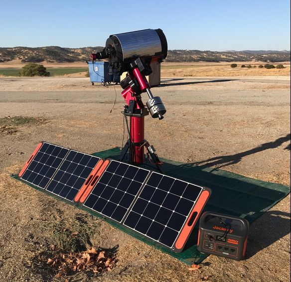 Actual Field Tests While the tests at my home observatory are telling, there is nothing like an actual test in the field. So, just after the October new moon and with clear skies at last I headed to a dark sky site along the central CA coast. I did not use the SSAG since I wasn't guiding and I also did not need the heater. However, for all three nights I powered my laptop with the Jackery as in Test #2 above for a completely self contained test of the Jackery. The first night I powered everything up at 6:17PM, just before dark and rough aligned on the crescent moon. As it turns out, my first night would be one of frustration as I learned after running a 120 point TPoint model that my PA was way off. It took a second TPoint run for me to realize that my daytime mechanical alignment was so far off that I had to rotate the entire mount and tripod and adjust the gross altitude pin on the mount to have any hope of an accurate PA. After 2 more TPoint runs I finally got a good PA and was able to begin imaging the M74 galaxy in Pisces at f/10. I typically dislike first nights in the field given my history of such self-inflicted wounds. My frustration actually provided a good power test since the mount spent a great deal of the first 4 hrs slewing back and forth across the sky more than 500 times. I powered down at 2:15 for a total run time of 8hrs with the laptop still fully charged and the Jackery at a SOC of 28%. In other words, I could have run for another 2 hours if I had been able to stay awake. During the next day I fully recharged the Jackery with the solar panels in about 6hrs so it was ready for the following night. I ran for 6hrs on the 2nd night completing my image collection of M74 and finishing with 50% SOC, easily recharging once again with the solar panels during the next day. The final night I ran for another 6 hrs finishing with 47% SOC as I imaged the edge on spiral galaxy NGC891 in Andromeda. Overall, the Jackery performed as I had expected allowing me to image for as long as 8-10hrs had I been able to stay awake, fully recharging each day with two 100w solar panels to be ready for the next evening. I was also able to use the Jackery during the day using its pass through charging feature to keep my cell phone recharged. Pass through charging allows the Jackery to simultaneously charge a device like the cell phone or laptop, while it is itself being recharged by solar or AC power. It will take correspondingly longer to recharge the generator depending upon the power used to recharge the connected device. Power Use Case Analysis Since everyone uses different equipment for their setups, I used the PPBA to measure the power requirements for each individual device and built the power consumption table shown below. Since my camera does not have cooling, I borrowed an ASI294MC Pro with cooing from a friend and measured the power requirements for three different degrees of cooling. Not surprisingly, the biggest power draw by far is my laptop and that is with the display turned down, Bluetooth and WiFi turned off. The camera cooler and dew heater on full are the next biggest power hogs. I find that I can usually run my heater at 50% with a dew shield and not have any dew problems, but others may find they need to run full power. Also, smaller OTAs will require smaller heater straps and correspondingly less power. The MyT mount power increases during slews but as I found when running TPoint in my field tests, 15w is a good average power consumption to estimate the total power needs for this mount if running by DC. In the past I measured the current requirements for a number of different mounts (CGE, CG5, Nexstar 6", ETX80 and IOptron Cube) and found that they use significantly less power than the MyT ranging from 2w to 6w during tracking. The ASI1600 is typical of cameras, including guiders, which operate on 0.5w or less without cooling. I do not have a powered filter wheel or camera rotator but I suspect that the power draw from those is negligible since they are used sparingly through the course of the night. 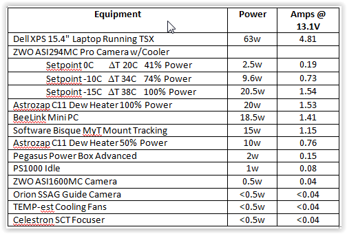 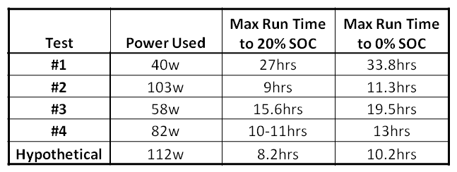 Taking these numbers into account, the following table summarizes the power required for each of my test cases and the corresponding maximum capable run time for discharges to 20% and 0% SOC of the Jackery. I added an additional case called "Hypothetical" which is identical to my Field test with the laptop powered by the Jackery up until the last 2 hours, but I added the additional power requirements of the dew heater at 50% power (10w) and a camera cooler at 100% power (20.5w) to get a total power requirement of 112w. One can see that for a setup that draws between 40 and 60w, fairly typical of an imaging rig using a mini-pc or a separately powered laptop, the Jackery 1000 can supply multiple nights of power without a need to recharge in between. Even in the most power hungry 'Hypothetical" case the Jackery 1000 can supply power for a long night of imaging. Additional Observations As noted above, the Jackery has a regulated power output. In my tests, the output voltage remained between 12.9 and 13.1V all the way down to 15% SOC showing excellent power stability. Another thing to note is that the drop in SOC was very linear with time, falling by the same % each hour all the way down to 15%. Like all other solar generators that I have investigated, Jackery specs the battery life to >500 full cycles after which the full capacity of the batteries will drop to 80%, or 800Wh for this particular model. At that point it will still supply 80% of its original capacity so one would still be able to get continued use out of it but the total run time would be shorter than during the first ~500 or more cycles. The Jackery can be used to power devices over the temperature range of 14deg F to 104deg F which will cover the typical star party season but might be a problem for hardy soles who like to observe away from home during frigid nights. Recharging of the Jackery requires a temperature above freezing, 32deg F, but I read of a clever trick where the generator is placed inside a cooler so that it stays warm enough under its own heat while recharging at temperatures below 32deg F. These are limitations typical of Li-chemistry batteries and it should be noted that the BMS will prevent the battery from being used outside these conditions so it cannot be accidentally damaged. Maintenance of the generator is simple requiring a discharge to 50% SOC and recharge once every 3 months. Summary I am thoroughly impressed with the build quality, performance and ease of use of the Jackery PS1000 as a source to power a typical astro-imaging session through a long night under dark skies. With the option to recharge within 7hrs by AC outlet and 8hrs by twin solar panels, if not less, I can look forward to eliminating those heavy lead acid batteries and avoid annoying my friends with my generator running through the night. The biggest downside to the PS1000 is its price. However, when I look at the cost of two 75Ah AGM batteries needed to match the Jackery's power, plus a quality pure sine wave inverter, MPPT charge controller for solar charging, power meters, USB charging sockets, cases, etc. I believe the cost of a DIY system easily exceeds $600 not counting the assembly effort. And one still has to carry two 50lb home built power supplies and connect them in series. Another consideration is that the Jackery can double as a backup generator in case of a power outage. The PS1000 will keep my refrigerator running for 9hrs before needing a recharge and, unlike my Yamaha generator, I can use it inside my house. For those with lesser power needs, say 40-60w the $499.99 Jackery 500 would be a lower cost option to achieve a 7-8hr imaging session. And for visual observers, the much less expensive 160 and 240w models would be more than sufficient for their power needs. I gave the folks at Jackery feedback on how they might make their generators more user friendly to the astronomy community. First, they might consider a 5.5mm x 2.1mm or an Anderson Power Pole DC output in addition to the cigarette adapter output. Or they could supply a cigarette adapter to 5.5mm x 2.1mm or Anderson Power Pole extension cable to make it easier to for us to connect the Jackery to our equipment. However, it was easy to find a cigarette to 5.5mm x 2.1mm power cord on Amazon that serves the purpose. The Jackery generator can be recharged with one or two of the Jackery Solar Saga panels in parallel or, with an MPPT to 8mm adapter with any solar panel under 30V and 10A. I plan to do a separate review of their solar panels in another blog soon so look for that soon. Pros High capacity and DoD Extremely light weight Voltage regulation Well designed and simple to use Simple to add solar recharging Cons Price Single 12V output No 5.5mm x 2.1mm or Anderson Power Pole output 500 cycles to 80% remaining capacity 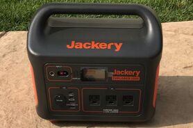 You may also want to watch my video review of the Jackery 1002Wh and 518Wh solar generator models on my YouTube Channel.
If you want to find out more about and shop for Jackery products, you can find them here Amazon.com. Links are Amazon Associate links. Jackery 1000 amzn.to/47DIVSm Jackery 500 amzn.to/47zeWep Jackery 240 amzn.to/3RX7QdM
4 Comments
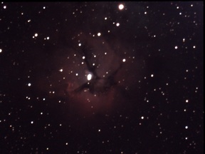
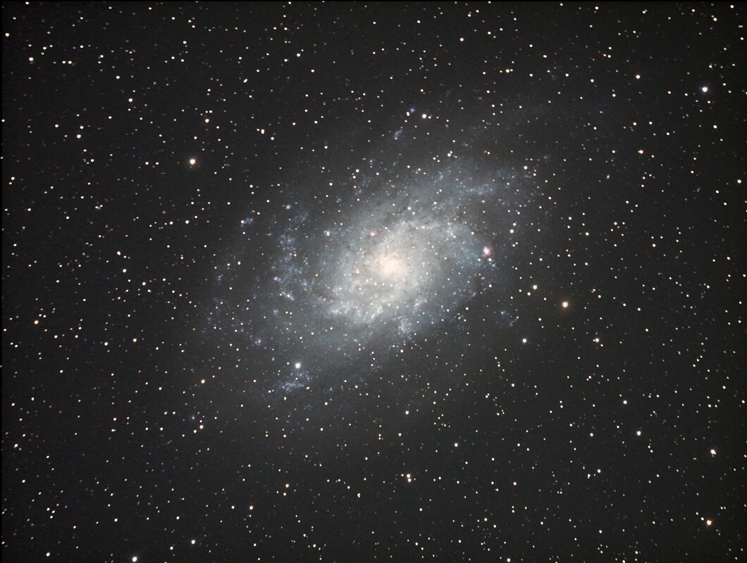 M33 C14 Hyperstar ASI1600MC 77 x 60sec Gain 139 Stacked & Stretched in Nebulosity M33 C14 Hyperstar ASI1600MC 77 x 60sec Gain 139 Stacked & Stretched in Nebulosity Never Over-Tighten Your Hyperstar I used the Hyperstar almost exclusively on my C14" Edge telescope with great success for years. Then one time I found that the Hyperstar would not unscrew from the secondary holder. No matter what I tried the Hyperstar was firmly attached to the secondary holder threads and would not come off. In fact, the more I tried to entice the Hyperstar loose I only succeeded in making the secondary holder spin in the corrector plate. Oh boy! What now? I reached out to Dean at Starizona who was a great help in solving my problem. He explained that the gasket that Celestron uses between the inside of the corrector plate and the secondary holder does not have sufficient grip and slips if the Hyperstar is tightened too much, as it was in my case. The solution, remove the corrector plate to get access to the backside of the secondary holder to release the Hyperstar. Once done, just replace the original gasket with a stickier one from Starizona and re-assemble. Well I did that but apparently I did not get the corrector plate centered on the primary mirror as well as I should have. How did I know that? Just look at this image I took of M33 and you will see that the stars in the corners are elongated in the direction of center indicating a collimation problem. Adjusting the secondary using the three screws was not sufficient to improve the collimation since the problem was that the secondary was no longer centered on the primary mirror. I read on CN about a technique using the circular rings formed by the primary mirror, baffle tube, secondary mirror and corrector when you look down the center of the optical tube as a guide to getting the corrector plate centered. The objective is to adjust the corrector plate using the screws on the outside of the optical tube (for Edge only scopes) until the ring of the corrector plate is centered. I tried this but found it too difficult to maintain a steady enough line of sight down the center of the tube to be certain how much I needed to adjust the corrector. I even tried setting up my iPad on a tripod to photograph the set of rings as shown in a YouTube video. But even this was not very successful for me. Apparently, this method does work for many people, but it wasn't going to work for me. The moral of the story ... snug is good enough for the Hyperstar! 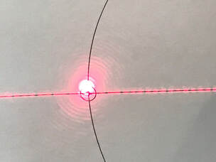 Before collimation of the CT collimator itself. Laser spot is off target slightly when reflected against a paper target as described in the CN blog. Before collimation of the CT collimator itself. Laser spot is off target slightly when reflected against a paper target as described in the CN blog. The HoTech Laser Collimator to the Rescue ... Not Quite Yet That led me to purchase a used HoTech Advanced CT Collimator on Cloudy Nights. The HoTech kit consists of a collimator plate, a Reflector Mirror with removable cap and a tripod adapter. There are four lasers on the back side of the collimator plate, one in the center and 3 at 120 degrees apart at a radius of several inches from the center. The laser in the center provides a cross-hair pattern for alignment of the plate to the telescope primary mirror. The 3 other laser provide parallel beams of light to simulate a distant star. The collimator plate has concentric alignment rings on its face for accurate collimation of the scope. The tripod adapter is used to attach the collimator plate to your own tripod and provides tilt of the collimator plate in two axes. The Reflector Mirror is inserted into the visual back or focuser to reflect the laser beams back to the collimator. If using the HoTech to collimate an SCT without Hyperstar this is all that is needed. When collimating with Hyperstar the optional Hyperstar upgrade kit is required as discussed below. Before attempting to use the CT Collimator I read a CN thread which indicated it was a good idea to check that the lasers on the collimator were themselves collimated before attempting to collimate the SCT. The thread provided a convenient method to do that using a paper target with a cross hair, a circle and 3 spots 120 degress apart where the lasers are positioned on the HoTech Collimator. The procedure is described here and works quite well. www.cloudynights.com/topic/647091-collimating-my-advance-ct-laser/?hl=%2Bcollimate+%2Bhotech+%2Bct#entry9088378 Using this method I came to the conclusion that one of my lasers was slightly off collimation. In principal, having found the offending laser I could adjust the laser myself to get it back in collimation. However, I was concerned that it was more likely that I might make it worse so I decided to send the collimator back to HoTech for adjustment. My only cost for the service was the postage. When I got the collimator back I set it up in my garage with the same paper target and verified that all three lasers were lined up where they should be. 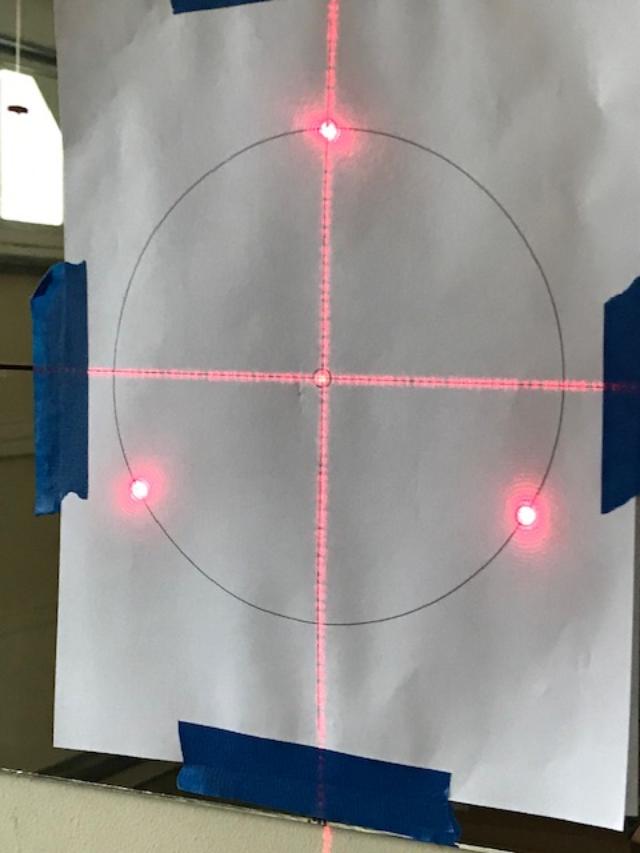 Cross hair and 3 laser beams reflected on the paper target showing perfect alignment after HoTech re-collimated the lasers. 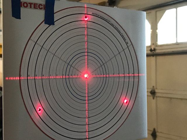 Using the mirror reflection method, the cross hair and 3 laser beams reflected back onto the collimator showing perfect alignment after HoTech collimation. The laser spot at the 4 O'Clock position is right on even if it looks slightly off in the picture which is an artifact of the off axis view. Using the mirror reflection method, the cross hair and 3 laser beams reflected back onto the collimator showing perfect alignment after HoTech collimation. The laser spot at the 4 O'Clock position is right on even if it looks slightly off in the picture which is an artifact of the off axis view. While waiting for my collimator to be aligned at HoTech I came up with another method to check the laser alignment using a small mirror instead of the paper target. Lining up the HoTech collimator 15 feet from the mirror and square to it enables the 3 laser spots to reflect off the mirror back onto the collimator. If the reflected laser spots all reflect back onto the lasers on the collimator, everything is in alignment. The advantage of this method is that the distance is effectively doubled providing greater precision. If you buy the HoTech Advanced CT collimator new you should not have this issue, but it is probably a good idea to check either using the paper target on the wall or the reflection from a good mirror. The originator of this CN blog insisted that I should not use a mirror as imperfections in the mirror would throw off the lasers. I understand that argument but if the reflected laser spots return to their origins as they obviously do in the image below after David at HoTech re-collimated the lasers, imperfections will not cause out of alignment lasers to appear in alignment. 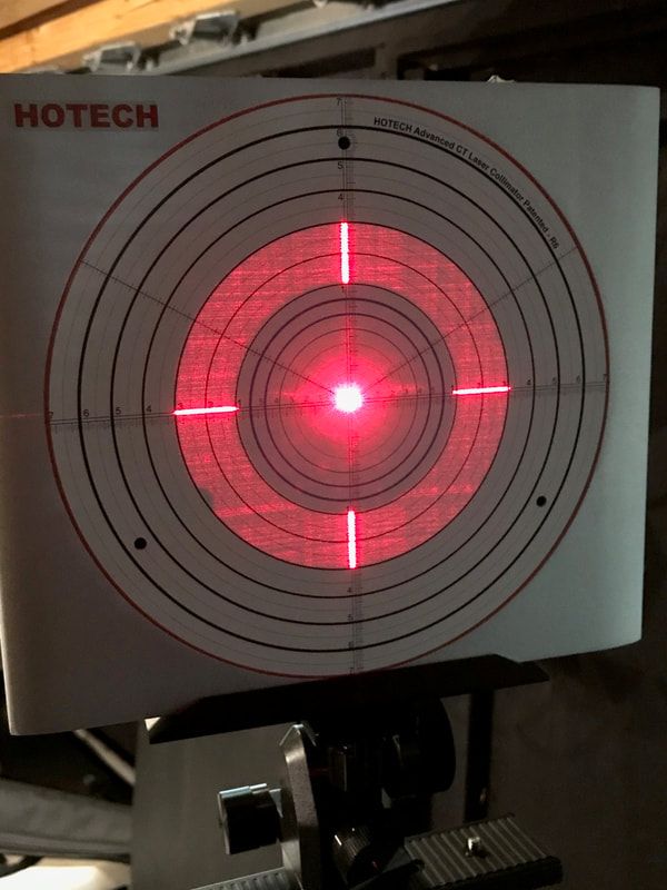 Both the cross hairs and the doughnut are visible. Both show alignment of the outer edges to one of the circles indicating co-planarity of the collimator to the primary mirror. The fact that the inner edges are also aligned to one of the circles means that the HyperStar (secondary) is centered on the primary. This image was taken on a brand new C11 Edge with perfect collimation. Both the cross hairs and the doughnut are visible. Both show alignment of the outer edges to one of the circles indicating co-planarity of the collimator to the primary mirror. The fact that the inner edges are also aligned to one of the circles means that the HyperStar (secondary) is centered on the primary. This image was taken on a brand new C11 Edge with perfect collimation. Mastering the HoTech Advanced CT Collimator Having certified that my collimator was in collimation I proceeded to the task at hand, to collimate my 14" SCT. Anyone who has used one of these will tell you that the initial step in the process is the most time consuming, tedious and most confusing step. And it is the most important step to get right. Once you get this done correctly, the rest is easy. Conceptually the first step is simple. Get the CT collimator plate in the same plane and on axis with the primary mirror. That is done by first attaching the HyperStar Reflector Mirror Assembly to the Hyperstar. The Assembly consists of an adapter ring, Reflector Mirror and a target cap. Next attach the collimator to a tripod with the included holder. The holder provides tilt adjustments along two axes which will be used to help align the collimator to the primary mirror. The following steps are performed with the collimator switched to Mode 1 using the center laser only to shine a cross hair pattern onto the telescope. Upon reflection from the primary mirror, this produces a clipped cross hair pattern on the collimator plate as seen in the image above. Next, adjust the height and distance of the collimator relative to the scope so that the cross hairs are centered and symmetric to one of the rings on the collimator. It is not necessary that the tips of the cross-hairs fall exactly onto one of the rings on the collimation plate, only that they be symmetric to the center of the plate. If the room is dark enough, you can also see a diffuse doughnut of red light from the laser collimator. Either the doughnut or the cross hairs can be used to do the alignment. Once either the cross hair or the doughnut is aligned, both will be aligned. I should note, that you will also move the telescope up and down or left and right to help align the collimator to the primary mirror. As the instructions say, repeat this process one or two more times but with smaller adjustments to get the alignment as spot on as possible. Also, it is best to set the collimator as far away from the front of the telescope as possible for higher precision. Typically it should be outside the Back Focal Length which is the point where the cross-hairs converge to a spot in the center of the collimator. You will notice that the inner edges of the cross hair (and doughnut) are clipped. This is due to the shadowing of the Hyperstar (or secondary). Likewise the outer edges of the cross hairs define the outer edges of the primary mirror. 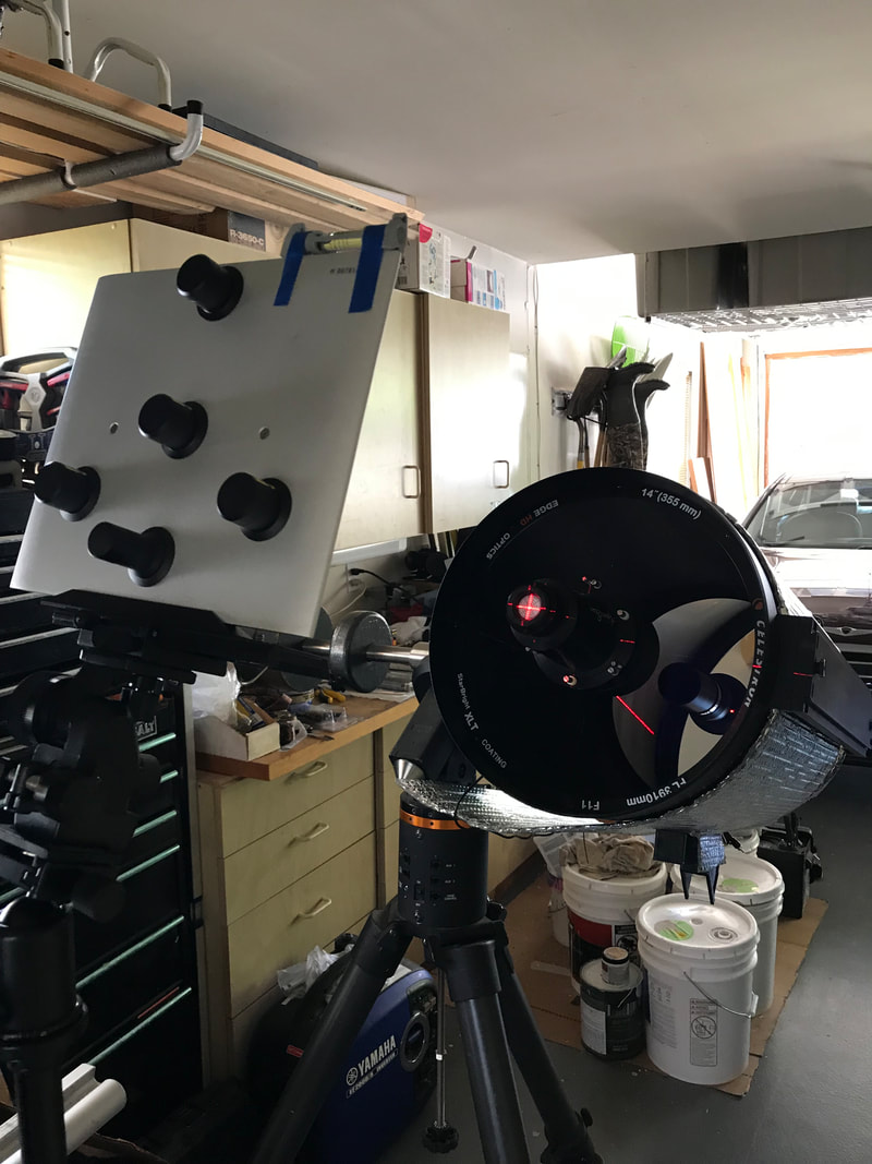 C14 with Hyperstar attached. You can see how the scope and Collimator are tilted at an angle to simulate actual star gazing conditions I should note that it is much better to do this process with the scope pointed upward, say 45 degrees, as it would be while observing. The weight of the mirror will cause a slight shift in position inside the optical tube when elevated which will change the collimation slightly if this procedure is done with the telescope pointing horizontally. I did this and found that unless you have a very tall tripod or a 8" and smaller SCT you will have to put the tripod on a table and tilt the collimator to the same angle as the scope. When set up like this, the process is even more confusing in terms of moving the tripod around to get co-planar alignment of the collimator and the mirror. But, eventually I succeeded. Having aligned the collimator plate to the primary mirror the hard part is done. You may have to re-check that you have not disturbed this alignment in later steps and re-adjust if needed. 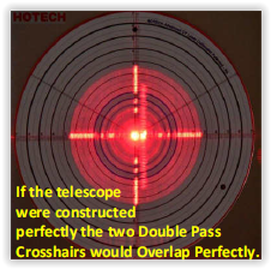 With the Reflector Mirror cap removed, a second cross-hair pattern is projected onto the collimator plate. The mis-alignment here indicates that the corrector plate is not centered. With the Reflector Mirror cap removed, a second cross-hair pattern is projected onto the collimator plate. The mis-alignment here indicates that the corrector plate is not centered. The next step is to make sure that the Hyperstar (or secondary if not using the Hyperstar) is centered on the primary mirror. Switch to Mode 2 which turns on the three lasers at 120 degree angles around the collimator plate. This creates three laser spots on the Reflector mirror target cap. Adjust the telescope focuser until all three dots converge into a single dot. If three spots are not all visible on the Reflector mirror target cap you will have to go back one step to realign the collimator to the primary mirror. Next, remove the Reflector mirror cap to allow a second smaller cross hair pattern to reflect from the Reflector mirror onto the corrector plate. This cross hair shows the tilt angle of the Hyperstar focal plane to the primary mirror. Adjust the push-pull pins on the Hyperstar to center this cross hair on the corrector plate. 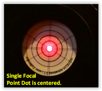 3 Laser dots on the Reflector Mirror cap aligned into a single dot. 3 Laser dots on the Reflector Mirror cap aligned into a single dot. The last step is to center the Hyperstar on the optical axis of the primary optical axis. Put the Reflector mirror cap back onto the Reflector mirror. The three laser spots should still be converged into a single spot. Next, this spot needs to be centered on the Reflector mirror cap. This is done on an Edge by loosening the screws on the front of the optical tube which hold the corrector retaining ring in place and then making use of the 3 adjustment screws on the outside of the optical tube to center the inner edges of the cross hairs on the same circle. If you do not have an Edge, you have to adjust the corrector manually until the secondary is properly centered. This completes the collimation process with the HoTech Advanced CT Collimator. The final step is to do a star test on a night with good seeing. Minor adjustments of the Hyperstar push-pull pins may be necessary to fine tune the collimation using the standard procedure for star collimation. When not using the Hyperstar, the process to align and center the secondary is different but is detailed in the HoTech Collimation manual and YouTube video which can be found in the links listed below. Also, when not using the Hyperstar, there is the added step of aligning the focuser to the optical axis. This procedure requires that the Reflecting Mirror supplied with the collimator be installed in the focuser and the secondary mirror removed so that a second cross hair pattern reflected by the Reflecting Mirror appears on the collimator screen. When this cross hair is centered on the collimator plate by adjusting the appropriate screws on the focuser, the optical alignment is complete. . 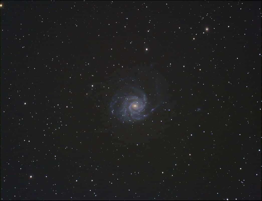 M101 116 x 30sec 200 Gain. Stacked and stretched in Nebulosity M101 116 x 30sec 200 Gain. Stacked and stretched in Nebulosity Collimation Confirmation
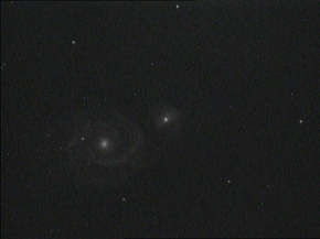
The final proof of good collimation was obtained by taking an image with the Hyperstar of a galaxy with lots of stars visible out to the edges of the field of view. Since much time had passed since I had imaged M33 to discover my collimation problem, it was no longer visible. So M101 was chosen as the test target since the FOV of the image has plenty of stars out to the edge to check for coma. As you can see in the image below, the stars are much improved at the four corners indicating much better collimation. While the HoTech Advanced CT Collimator is both expensive and requires a steep learning curve, it works extremely well allowing collimation during the day time or on a cloudy night. Unlike a star test, it also provides the ability to check the centering of the Hyperstar (secondary) and the alignment of the focuser to the optical axis of the primary, both of which can cause problems with star shapes when they are out of alignment. If you choose to use the CT Collimator, remember to be patient the first time you do it and use the helpful documentation in the links below. Good luck! If you are interested in the HoTech CT Collimator you can find it here. Make sure you get the right : HoTech CT Laser Collimator - 2" collimator with accessories HoTech CT Laser Collimator - 1.25" collimator with accessories 1.25" Reflector Mirror - separate mirror for a 1.25" opening 2" Reflector Mirror - separate mirror for a 2" opening OPT links are Affiliate links. Helpful Links HoTech has made a very helpful video which shows each step of the collimation process but with the secondary mirror in place, not the Hyperstar. It can be found here: www.youtube.com/watch?v=4BDwa0RVZw0 The complete written collimation instructions with illustrations, for both the Hyperstar and non-Hyperstar setups can be found on the "Helpful Links" page of this web site. There is also a CN thread showing a clever homemade jig to help make the collimation process easier which can be found here: www.cloudynights.com/topic/697589-learnings-from-using-hotech-laser-collimator-with-edgehd-scope/?hl=hotech+ct+collimator 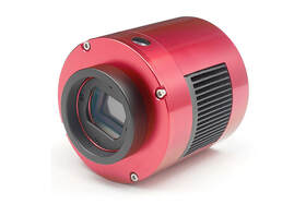 The introduction by ZWO of their camera, the ASI1600, in early 2016 has been a game changer for Camera Assisted Viewing (CAV), also known as Electronically Assisted Astronomy (EAA) or Near Real Time Viewing. This camera was the first astronomy camera to use Panasonic's latest CMOS sensor, the MN34230. The 4/3 format sensor has 16.3 Megapixels (4644 x 3506), each 3.8 microns square with a total chip size of 17.6 x 13.3mm. The larger chip size has a diagonal of 22mm which provides a much larger field of view compared to the cameras commonly used for CAV . Compare this to the analog cameras from Mallincam which have less than 0.5 Megapixels and diagonals of only 6 and 8mm depending upon the camera model. Even the recent CMOS cameras like the ASI224 only has 1.2 Megapixels and a diagonal of 6mm, much smaller than the ASI1600. And with 3.8 x 3.8 micron pixels it provides high resolution images for excellent image detail. Additionally, this sensor supports extremely low read-out noise on the order of 1 electron which made stacking many very short exposures much more practical. This reduces the demand on the quality of the polar alignment and the mount tracking for a successful CAV session. With such a large sensor and 16 million pixels, this chip supports binning 1x1, 2x2, 3x3 and 4x4 which trades resolution for sensitivity by making the "effective" pixel size larger. This is also useful in tailoring the image scale (arc-sec/pixel) to different optical setups. 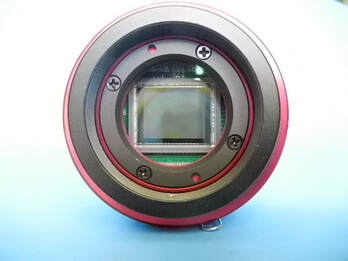 Panasonic's new sensor was quickly incorporated into new cameras from ZWO, QHY, Mallincam and others and soon took the CAV community by storm making these the new hot cameras to have. ZWO was the first to incorporate this sensor into its ASI1600 camera which came in both uncooled Color ($699) and Monochrome ($899) versions. The uncooled color camera is now discontinued, but still can be obtained on the used market. They later came out with a cooled Monochrome version ($1280) called the Pro with 2 stage cooling down to -40deg, a 256MB DDR3 memory buffer to help avoid lost frames during high rate data transfers, a USB3.0 port and a USB2.0 Hub to connect accessories such as a filter wheel, guider and a focuser. The camera also has an autoguider port in case you want to use it as a guide camera. 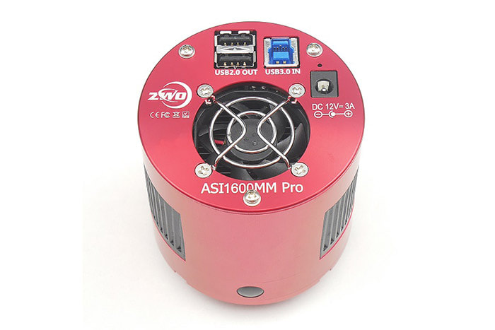 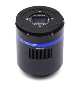 QHY and Mallincam soon followed with similar cameras of their own incorporating this new Panasonic sensor. The QHY163 comes in color ($899) and monochrome ($1199) versions and also includes 128MB of DDR memory, a USB 3.0 interface, guide port, two stage cooling to -40C cooling and a sealed chamber with a heated window to prevent dew from building up. Mallincam's SkyRaider DS16 comes in 3 versions, color ($999), monochrome ($1299), both with a fan for passive cooling and TEC version ($1700 color, $1900 monochrome) with active cooling. They all have a USB 3 interface, a sealed chamber, DDR memory and a full featured software, Mallincamsky, for camera control, capture, live stacking and dark frame subtraction. The TEC version includes a USB Hub and a heated window for dew prevention. Both the ZWO and QHY cameras use the free software Sharpcap which performs all of the same functions as Mallincamsky and much more if you pay for the Pro version, but that is a topic for another blog. There are still more versions of cameras incorporating the Panasonic 4/3 chip, but I will not list all of them here.  These new cameras appear to have had two major impacts on the way we do real time viewing.
First, if you read the threads on the Cloudy Nights forum, you will see that many amateur astronomers have moved away from the long exposures of 30 sec to minutes common with the security type astronomy cameras like the Mallincam Xtreme and Xterminator or the Revolution Imagers 1 and 2. With such low read-noise it is now practical to use programs like Sharpcap to stack many very short exposures of a few seconds on the fly to get as good or better image after 30sec to minutes but with less demand on the quality of the mount and the polar alignment. In fact, Alt-Az mounts become even more practical for CAV with such short exposures and the use of an on-the-fly stacking program. This can both minimize the cost of the setup and reduce the overall hassle in getting a good polar alignment. Obviously, a better mount and more time spent on a good polar alignment will improve the experience, but less so with exposures of 2 to 5 sec which is now practical with this new sensor. Second, since the pixels are square not rectangular stars are round unlike their appearance with CCD analog cameras and they do not have the black halo common to stars in images taken with analog cameras. Also, with pixels about 1/3 the size of the pixels in analog cameras much more detail can be seen in galaxies and nebular with the new sensor. Images obtained are of much higher quality than ever before. The net result appears to be a move by many CAV folks more and more in the direction of traditional astrophotography. It has become increasingly the case that dark frame subtraction and even flat frames are both employed with on-the-fly stacking to get the best possible image. The ideal case is to be able to view the image in real time to get the immediate enjoyment of observing deep sky objects, while saving individual frames for later post processing to obtain an astrophotography quality image. In fact this can be done with Sharpcap using the Live Stacking feature while selecting the option to save individual frames in FITs or PNG format for later post processing. As is always the case, time marches on and even newer products come to market. It appears that the successor to the ASI1600 is the ASI294 with the Sony IMX294 CMOS chip. It too is a 4/3 sensor with extremely low read noise. Even thought it has less pixels at 11.7 Megapixels, the major new advantage of the ASI294 is it's much deeper well which provides a significant advantage for dynamic range. Perhaps a topic for a later blog. I have been using the ASI1600MC for the last two years and am very happy with it. However, only the mono versions are still available. My astro buddy uses the ASI294MC color cooled version and has had great success with it. You can find the products listed in this blog in the links provided below. As an OPT Affiliate I can earn from qualifying purchases through my site with no additional cost to you. This helps to defray the cost of this website. ZWO ASI1600MM Uncooled - this is the mono version of the camera I have ZWO ASI1600MM Pro - cooled mono version of the camera I have QHY163 - QHY's cooled version of the color camera I have ZWO ASI294MC Uncooled - this camera is one of the most used cameras for EAA ZWO ASI294MC Pro - this is the cooled version of the 294 Revolution Imager II - analog camera which I have used and reviewed elsewhere 
Many people who do video astronomy like the option of keeping things as simple as possible. This is one reason to choose an analog video camera at a time when many are moving to digital video cameras like those from ZWO. The analog cameras do not require a computer unlike the digital cameras. An analog camera only needs a video display device which will accept an analog input. A light weight 7" or 9" LCD will suffice for viewing by 2-3 people. Simply connect a video cable between the camera and the display to view images. The camera can be controlled with the 5 control buttons on its back, or with a hand control if the camera is configured for one.
But what if you want to ditch the video cable and LCD monitor to further simplify the setup? That is quite easily done with a WiFi Emitter and your phone or tablet making the gear requirements including power all that much simpler. The WiFi Emitter connects to the camera analog video output and is compact and lightweight enough to be attached to the telescope with the accompanying double sided adhesive. It can be powered with the same 12VDC battery used to power the camera further minimizing the number of required cables. If both the WiFi Emitter and battery are attached to the telescope there will be no need for long cables nor any concern about cord wrap or snags on the mount, etc. The WiFi Emitter works with Android and Apple devices, both phones and tablets and is very simple to setup and connect. With this you can view your video images on your cell phone or tablet completely untethered by cables over distances of 150ft or more depending upon intervening obstacles. I was able to connect to my camera in the back yard from inside my house. If you also have WiFi control for the telescope mount, say through Sky Safari or similar, this setup makes for a very comfortable viewing from inside your home. 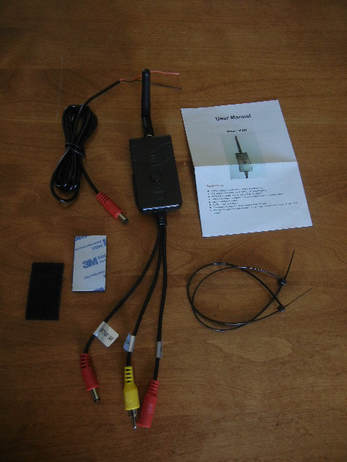
You can get a WiFi Emitter from Orange County Telescopes (OCT), the home of the Revolution Imager 1 and 2, for $90. If you are more of a DIY person you can obtain one on Amazon for less than $40 if you search for"AV WiFi Emitter". The WiFi emitter comes with 3 short cables hard wired to the unit, a screw on antenna and an instruction book. The one I bought from Amazon also came with double sided tape which I used to attach the emitter to my camera but you could also attach the emitter to your scope instead. It also included plastic cable ties and another power connector in case I wanted to hard wire the power input to a power source. The emitter sold by OCT does not have the tape, cable ties nor the extra power connector but does include an RCA to BNC adapter which is needed to connect the emitter to the camera. If the emitter you purchase does not have this adapter, you can purchase one on Amazon for a couple of dollars.
The emitter has three short cables. The yellow cable connects to the video output of your camera. This cable has a male RCA jack so you will need an RCA to BNC adapter to make this connection. The other two cables are red and are for the power connections from the battery and to the video camera. Connect the power from your battery to the red input connector which has a female DC plug and connect the other red cable with a male DC plug to the power input of your camera. The WiFi unit runs on 9 -30V DC so a simple 12V battery used to power your analog camera will suffice to power it as well. 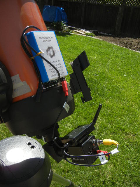
A one time setup of the required software is necessary to get started. Using you phone or tablet connect to your APP store, simply search "WIFIAV" software and install it. For iPhones and tablets this would be the Apple Store and for Android phones and tablets this would be the Google Play Store. You will see an icon on your phone that looks like the emitter broadcasting a signal from the antenna. This is the app you will need to launch whenever you want to connect wirelessly to the camera.
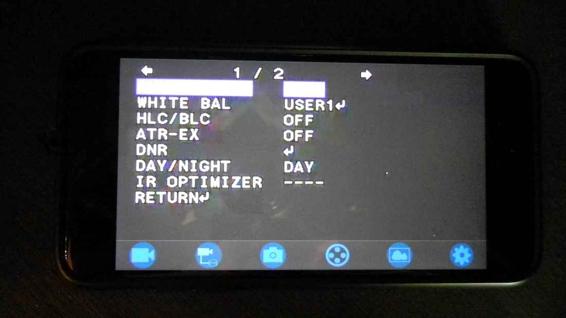
When you are ready to connect to your camera, turn on the power to your emitter and camera and you should see the Red LED on the emitter light up. Next, push the button on the emitter and you should see the green "Link" LED on your emitter light up. Now go into your phone or tablet settings and connect its WiFi to "WIFIAV". You may need to type in a password the first time you connect which is probably "12345678", and will be included with the instructions which came with the emitter. Launch the WIFIAV app on your phone or tablet and you will see a screen with 6 blue icons at the bottom and an image from your camera if you are already pointed to an object and focused. Or, you may see the camera menu screen if you have enabled that. Shown here is the camera menu for the Revolution Imager 2. At the bottom of the screen are 6 WiFi controls to capture a video, record to a DVD, save an image, check the emitter signal, go to a file folder which contains the saved images and videos, and change settings. If you plan to only view images live you need not use any of these. If you would like to save images to your phone or tablet just click on the camera icon. You can retrieve these using the file folder icon. 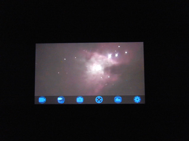
You are now ready to view images from your camera remotely. Just move your telescope to the object of interest and adjust the camera settings as you normally would and you are ready to view objects from planets to DSOs wirelessly on your phone or tablet. While this device makes wireless viewing a simple reality, I have to say that the image quality is definitely not as good as what I can see with the video hard wired to an LCD. I believe there is some video compression which occurs in the wifi transmitter which causes this. Nonetheless, this device enables one to step away from the telescope, view effortlessly from inside or walk around at a public outreach event and share images live without having to crowd around the telescope.
You can find the WiFI discussed in this blog and which I use in the link provided below. As an Amazon Associate I can earn from qualifying purchases through my site with no additional cost to you. This helps to defray the cost of this website. 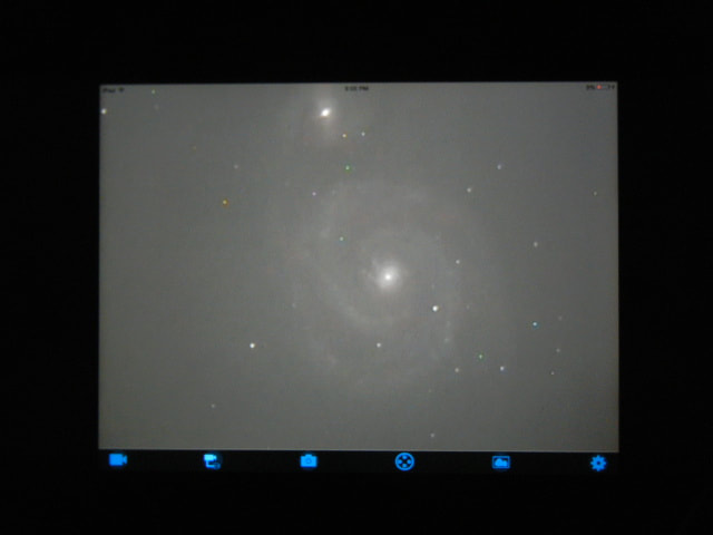
 ASI224MC ASI224MC Nearly two years ago I obtained my first USB camera, an ASI224MC sold by ZWO. ZWO had introduced this camera in July 2015 for $350 and it was an immediate hit with the EAA crowd for good reason. The ASI224MC uses a 1/3" format Sony IMX224 color CMOS sensor with 1.27 Million 3.75 micron square pixels. This provides round, pin-point stars with high resolution unlike typical analog video cameras which have rectangular and much larger pixels. With a high sensitivity rated at 2350mV this Exmor sensor combined with an extremely low read noise of 0.55e to 3e means (depending upon the gain) the camera is well suited to live stacking of many short exposure images. This is very helpful for Alt-Az mounts where single frame exposure lengths are limited by field rotation to around 30sec. When combined with the powerful and free Sharpcap software this camera shows great detail in a wide range of deep sky objects. Since this is a USB camera and not an analog camera, a computer is required to operate the ASI224. A single USB cable from the camera to the computer is all that is required for both camera power and control. One less cable to deal with and to potentially snag on the mount compared to analog cameras is a pleasant advantage. Sharpcap is probably the most commonly used software for the ASI224 and it provides control over all of the camera menu settings. It provides for image display, capture, histogram stretching, dark frame subtraction and on-the fly alignment and stacking among other nice features. Sharpcap can be downloaded from the ZWO web site along with the native driver necessary to connect the camera to the computer. To use other software you will have to load the ASCOM driver also available on the ZWO website. Camera settings include an exposure range of 32micro-sec to 1,000sec which makes the camera highly capable for both planetary and deep sky viewing. The camera has a gain setting range of 0 - 450. Lower gain provides higher dynamic range while higher gain provides the lowest read noise. Typically, people report working with gains in the range of 300 - 350. This camera also has the capability for 2x2 binning which makes the pixels effectively 7.5 x 7.5 microns, increasing the sensitivity and speed of the camera at the cost of resolution. 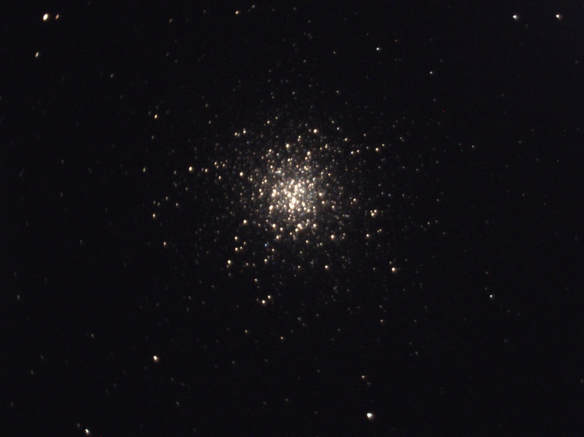 ASI224MC: M13 8sec 350 Gain, Celestron 6SE @~f/4.5 at Dark site ASI224MC: M13 8sec 350 Gain, Celestron 6SE @~f/4.5 at Dark site With a sensor diagonal of 6.09mm, the ASI224 has a field of view and magnification factor similar to a 6mm eyepiece. This can make it challenging to place a faint object in the field of view unless the mount's GoTo alignment is very good. The ASI224 comes with a 2m USB cable to connect the camera to a computer along with a 1 1/4" nose piece adapter to connect the camera to the telescope like any eyepiece. It also comes with an f/2 all sky lens with a 151 degree field of view for detecting meteor showers. This must be removed before attaching the 1 1/4" nose piece. The ASI224 is also designed to work as an autoguider when used with a program like PhD. As such, it has an ST4 guide port and comes with a 2m cable to connect to the mount. While the camera comes equipped with a 1 1/4" nose piece to fit inside a standard 1 1/4" focuser like any eyepiece, the camera can also be inserted into a 2" focuser since the camera body has a 2" diameter collar in the front. This is helpful to achieve additional in-focus when using Newtonians and Dobsonians which are not designed for astrophotography. In addition, the front of the ASI224 has an M42 x 0.75 thread making it ready to be used with T-adapters. 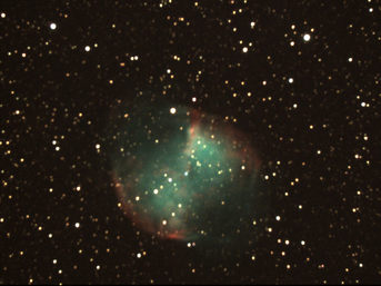 ASI224MC: Celestron 9.25" SCT @ f/4.5, M27 Dumbbell Neb. 6 x 20sec Stack Gain 350. Dark Site ASI224MC: Celestron 9.25" SCT @ f/4.5, M27 Dumbbell Neb. 6 x 20sec Stack Gain 350. Dark Site The ASI224C was upgraded in April 2016 with anti-amp glow circuitry. Amp glow is caused by the heat produced in the read out circuit of the sensor during long exposures and is common in analog video cameras. It produces a bright glow at the edge of the image making that part of the object appear over-exposed. Short exposures and/or dark frame subtraction are commonly used to eliminate or minimize the impact of amp glow. With the ASI upgrade this is no longer necessary. The USB connection was also upgraded from USB2.0 to USB3.0 to support better download rates. In addition, the price of the ASI224 has been reduced to $249.99 as other cameras with the IMX224 sensor have become available. A cooled version of this camera, the ASI224MC-C was available for a while and sold for $599, but has since been discontinued. As can be seen from the images here, the ASI224MC camera performs very well for all sorts of deep sky objects. It produces nice round, pin point stars and has very good color saturation. All images were captured using Sharpcap and have had no post capture image processing. What you see here is what you would have seen on my computer screen live. 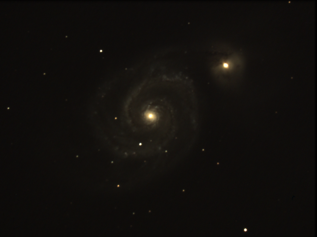 ASI224MC: Celestron 9.25" SCT @ f/4.5, M51 Whirlpool Galaxy 74x 5 sec Stack Gain 350. Dark Site 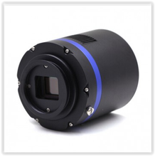 QHY224C QHY224C With the popularity of the ASI224MC, many other camera suppliers have introduced versions of their own with the IMX224 sensor in the last couple of years. QHY makes and sells a cooled camera with the Sony IMX224 sensor for $669. It's 2-stage regulated TEC cooler can cool to 40deg. C below ambient. It also has the anti-amp glow circuit, a USB 3.0 computer interface and a 128MB image buffer to prevent lost frames when capturing images with a high frame rate. This camera has exposure settings of 7micro-sec to 400sec and the same read noise as the ZWO camera. With the active cooling, the QHY camera body is significantly larger than the ZWO but it also has an M42 x 0.75 thread making it ready to be used with T-adapters. 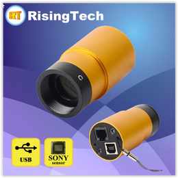 Model GPCMOS Model GPCMOS While ZWO and QHY make their own cameras with the Sony IMX224 sensor, there are many other retailers who appear to re-brand cameras from a Chinese company called Touptek and sell them under their own label. These include three cameras from Rising Tech in China, and one each from Mallincam in Canada and the U.S., Orange County Telescopes in the U.S. and Altair Astro in the U.K. Rising Tech sells three versions of the IMX224 based camera. The USB 2.0 version, Model GPCMOS, comes without the amp glow reduction and sells for $162 making it the cheapest IMX224 based camera currently on the market. This camera also has a lanyard which can be used as a safety strap to attach the camera to the scope. Model G3M224C has the USB 3.0 connection and the amp glow reduction circuit for $245 and has a slightly larger body than the GPCMOS camera. However, both models are small bullet shaped cameras which can fit well inside a focuser making it easier to achieve focus with Newtonian telescopes which are not designed for astrophotography. Model G3-1200KPA also has both the USB 3.0 and the amp glow reduction, but comes with a cooling fan for $295. The G3 also has a much larger camera body and has M42 X 0.75 threads making it straightforward to attach a t-adapter to the camera. All cameras come with camera control software called Rising Sky, which appears to be a re-branded version of Toupsky camera control software. Toupsky has many of the same features found in Sharpcap such as image display and capture, on the fly stacking, dark frame subtraction, histogram stretching, etc.
 Mallincam's IMX224 camera is called the Skyraider AG1.2c, and comes with a USB 2.0 computer connection, MallincamSky software which looks like re-branded Toupsky software for $250. The Skyraider camera body has built in cooling fins to facilitate passive camera cooling and also has a lanyard which can be used as a safety strap to attach the camera to the scope. The web site makes no mention of amp glow reduction so I assume it does not have it. The bullet shaped front also enables this camera to fit further into a focuser making it possible to achieve focus where some of the larger cameras cannot.  ASI224MC: Celestron 9.25" SCT @ f/4.5, M57 Ring Nebula 6 x 20sec Stack Gain 350. Dark Site 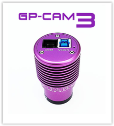 Altair Astro's GPCAM3 224C has a USB 3.0 computer interface and comes with a UV-IR filter and AltairCapture software. The camera body has cooling fins and the same bullet shaped front as some of its competitor. The GPCAM3 sells in the U.K. for £249. It also comes with a 1 year license for the Pro Version of Sharpcap. Orange County Telescopes sells the Revolution Imager 224 (R224) but does not hide the fact that this USB 2.0 camera is manufactured by Touptek. The R224 makes no mention of the amp glow circuitry, comes with the ToupSky software and sells for $250. The R224 is another of the bullet style cameras. It comes with a UV-IR filter, a 0.5X focal reducer and a soft carrying case for the camera, cables and accessories. 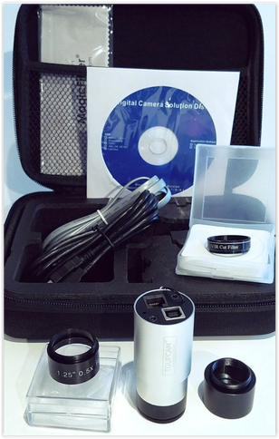 Revolution Imager224 Revolution Imager224 Maximum exposures are 1,000sec for all of these cameras, but the stated minimum exposures vary. While several of the camera suppliers do not specifically mention the read noise, I believe these all have the same read noise specs which are determined by the CMOS sensor itself. All of these cameras come with a 1 1/4" adapter to connect the camera to a 1 1/4" telescope focuser and a USB cable to connect to a computer. They also all have the standard ST4 guide port to use as an autoguider and guide cable. Some come with additional adapters and some also have T-threads to attach T-thread adapters. All should work with the Sharpcap software but may need the ASCOM driver to do so. Any of these cameras should function well as a low cost camera for real time viewing of the deep sky with the added advantage as an autoguider if and when you move on to a more expensive camera. 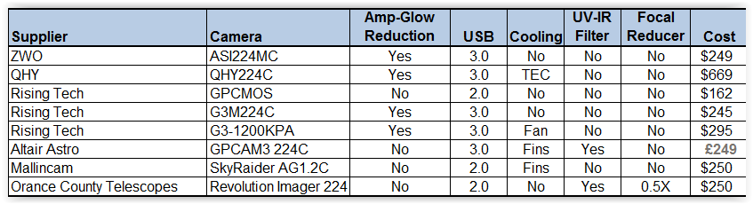 
Over the years I have always used an EQ mount along with my Celestron 9.25" SCT, Celestron 14" SCT with Hyperstar or my Orion ED80 (for wide field images) when engaging in deep sky video. However, such setups are heavy, not easy to transport when traveling to a dark site or just setting up nightly in one's own back yard. Also, these scopes and mounts are fairly expensive, counted in the many thousands of dollars not including the video camera. In addition, polar aligning an EQ mount is not everyone's cup of tea, let alone accurately aligning it for long exposures.
There seems to be a lot of interest lately in very light and highly portable Electronically Assisted Astronomy (EAA) setups which do not cost a fortune. Some are experienced astronomers who are downsizing as they are getting older and finding it more difficult to transport and set up heavy equipment. Some want a simple setup for public outreach. Others are new to astronomy and want to start with something simple to setup, easy to get started and relatively light on the wallet. To address this trend, I paired a Celestron SE6 which is a 6" SCT on an Alt-Az mount with two different types of low cost video cameras, a Revolution Imager 2 (R2) and a ZWO ASI224MC. 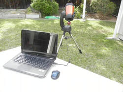
Why the choice of the SE6? Alt-Az mounts pose a fundamental challenge since they don't track along the Celestial Equator like and EQ mount does. This means that objects do not stay centered in the field of view (FOV) like they do in a polar aligned EQ mount. Field rotation, which causes stars to become elongated and blurs detail in extended objects like galaxies and nebulae, can limit exposures to as little as 10 seconds in some parts of the sky. The length of the exposure possible before field rotation becomes a problem depends on the focal length of the telescope, the Altitude and the Azimuth of the object being viewed, and the observer's latitude. You can read more on this in the "Quick Start Guide" section of this web site. Fortunately, recently released EAA software has the ability to extend exposures to several minutes without field rotation ruining the image.
Second, Alt-Az mounted scopes are typically much less expensive than EQ mounts which addresses the lower cost factor. The 6SE, which belongs to the Celestron Nexstar series of scopes typically sells for $799 including the mount, tripod, SCT and accessories. I have seen it on sale for $699. The 5SE, with a 5" SCT is $100 cheaper. Third the 6SE meets the objective of lightweight and portable with a weight of only 21lbs counting the mount, tripod and scope. The 5SE is only 17.6lbs. Because of this and the fact that the mount and scope are fairly compact, I was able to leave everything assembled and move it back and forth between my house and the yard easily and quickly. For transport to a dark site, the scope disassembles into three pieces (tripod, mount, SCT) and easily fits into the trunk or back seat of practically any car. A plastic accessory box serves to hold the camera and its accessories. Fourth, there is no requirement to polar align an Alt-Az mount which makes it much easier and faster to setup than an EQ. First, level the scope. Next, the Celestron Nexstar series of scopes has a Skyalign routine which requires sequentially locating three bright stars or planets using the included unity Red Dot Finder and the hand control to move the scope in Altitude and Azimuth. Each star must be centered in the FOV of the camera or an EP. Once all three have been found, Skyalign will determine the scopes orientation and even tell you which three objects you found. To obtain a good alignment, the three objects should be widely spaced and not in a straight line from one another. With the scope aligned, it will be able to GoTo nearly 40,000 objects in its on-board memory and will be able to place most objects in the FOV with a 12mm or larger EP. For video cameras with 1/3" CCDs, I found that some objects were just slightly out of the FOV due to the small size of the CCD chip, but typically they are outside the FOV in the same direction which makes it easy to make small adjustments with the hand control to get the object centered. With practice, the Skyalign GoTo alignment can be completed in less than 10min. Fourth, the 6SE comes with a 6" SCT which I think is sufficient for observing all of the Messiers and many of the Herschel objects with either of the two cameras listed above. An 8" version will show much more and is recommended if it is within budget since it only adds 3lbs to the total weight. The 5" version will still provide pleasing views for those on an even tighter budget.
Why the R2 and the ASI224MC? Simply cost and performance. The R2 which comes as a kit costs $300 and the ASI224 is $349, making these two of the lowest cost options for EAA. Both perform extremely well, each offers advantages over the other and both are color cameras.
The R2 is an analog camera which comes as an all-in-one kit including a 7" LCD, Li Ion battery, focal reducer, UV-IR filter, hand control and cables. This is everything you need to get up and running immediately. And, it has a reasonably sensitive CCD which will provide pleasing images of many deep sky object. The camera settings are changed using the hand control and on screen menu display. Since it is an analog camera it can be hooked directly to the LCD or your own larger television set and does not need a computer to work. This makes the combination of this camera and the 6SE highly portable. On the other hand, with the addition of an inexpensive digital capture device the R2 can be connected to a computer to capture and process images. With free EAA software such as Sharpcap, the maximum exposure can be extended to several minutes as will be explained shortly. The ASI224MC is a USB camera which comes with a USB cable, C-Mount and T-mount adapters and an All-Sky lens for wide angle shots of the night sky. A computer is required to adjust the menu settings, view, capture and stack images live. A single USB cable connected to the computer, powers the camera, sends images to the computer and provides control of the camera menu. Sharpcap can also be used with the ASI224MC to do everything it can with the R2, plus it will control the camera settings as well. If you prefer, a version of the software package AstoLive is available free to anyone purchasing a ZWO camera like the ASI224MC. With a very low readout noise, the ASI224MC is well suited for stacking of many short exposure frames. And, if you decide to move up in cameras later, the ASI224 can be used as an autoguider. The ASI224MC will require the purchase of a focal reducer to improve image detail and one equivalent to that provided with the R2 can be purchased for less than $20.
I attached the R2 to the SCT with a 1.25" diagonal to give enough space for the camera to clear the mount when pointed at the zenith. The Hand Control for the R2 is attached at the back of the camera when I view on the LCD. When I use a computer, I use a longer video cable and connect the Hand Control next to the video capture device at the computer. Using these two different methods enables me to have the Hand Control right next to me. For the LCD, I bent the mounting base to the curvature of the the optical tube assembly (OTA) and glued a piece of soft foam to the bottom of the mounting base to avoid scratching the finish of the OTA and held it in place with Velcro straps. I can change the angle of the monitor to compensate for different OTA orientations. I mounted the battery to the arm of the Nextstar SE mount and ran the power cable to the monitor and camera using the included power splitter cable. The mount can be run on its own internal batteries or with an external 12V battery. With this setup, I can leave everything connected and stored inside my house and very easily carry it outside and set it up, including the GoTo alignment in about 15 minutes.
The ASI224MC can be attached directly to the visual back without a diagonal and will easily clear the base of the mount when pointing at the zenith. The ASI224MC requires the use of a computer and software to control the camera, view and save images. The included USB cable simply connects to one of the USB inputs on the computer. With the exception of the computer, this setup is even simpler than with the R2. But then, some folks do not want to have to deal with a computer, especially in the field.
When using a computer, the last important piece to this EAA setup is the free software, Sharpcap. Sharpcap not only allows one to view, capture and adjust the brightness and contrast of images live on the computer screen. It can also stack frames on the fly, translating and rotating successive frames to align them to the original frame. This greatly extends the exposure times possible with an Alt-Az mount into the many minute range. Sharpcap also has a histogram feature which enables stretching of the image to bring out more detail and darken the background sky. All of this on the fly, and for free.
So there you have it, two light weight and highly portable EAA solutions which won't break the bank. What are you waiting for, get going!
Another good option in highly portable and lightweight scopes for EAS is the Celestron Nexstar 6SE which is slightly more expensive but has a better mount than the regular 6SE. If you are interested you can click on the link below to take you directly to a supplier. As an Amazon Associate I can earn from qualifying purchases through my site with no additional cost to you which helps to defray the cost of this website. 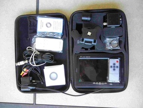
A beginner getting into video astronomy typically purchases a camera with a few essential accessories such as power and video cables and a nose piece adapter. However, this leaves it up to the individual to research and purchase additional important accessories such as a focal reducer, filters, a monitor and a 12V power source. For many of us this is not a problem, but for some it is a hassle and can be downright confusing considering the different decisions that have to be made and the fact that these have to be purchased from many different sources. This may discourage some making them choose to move onto something else.
Fortunately, last year an astronomy supplier in Southern California, Orange County Telescopes (OCT), put together a complete package with all the necessary pieces required to get started with no hassle and at a reasonable cost of $300. The package was called the Revolution Imager and it contained an Lntech 300 PAL video camera, power and video cables, a 0.5X focal reducer, an UV-IR filter, a 1.25" C-Mount adapter, a 7" LCD monitor, a hand-held camera remote control, a 12V Li ion battery with charger and a convenient shock resistant carrying case. Here, in one complete package, was everything needed to get started viewing planets, galaxies, nebulae and other deep space wonders except the telescope and mount. The Revolution Imager apparently was a hit with beginners, as well as, those who already had a video camera but wanted something simple for themselves or for use at public outreach events. Eventually the packages sold out as production of the Lntech 300 came to an end. 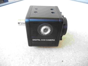
Fast forward to May 2017 and OCT has once again put together an all-in-one package after finding a replacement for the original camera. The new package comes with all the same accessories as before and still sells for $300. It is called the Revolution Imager 2 (R2). The new camera uses the same Sony ICX811 PAL 1/3" CCD as the Lntech 300 which is one of the more sensitive CCDs used in video cameras today. It outputs video with a resolution of 720 x 576.
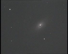
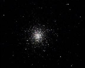 M13 9.25" SCT Backyard 5sec M13 9.25" SCT Backyard 5sec
So how does the R2 camera and all of the accessories perform? In my opinion, quite well. I tested the R2 from my backyard with both a Celestron 9.25” SCT on an equatorial mount and a Celestron 6” SCT on an Alt-Az mount and obtained very nice images of globular clusters (M3, M5, M13), galaxies (M51, M63, M64, M66, M87, NGC5907) and the planetary nebula M57 with both setups. I initially viewed images directly from the camera on the included 7” LCD monitor and powered both the camera and monitor with the included Li Ion battery. Later, I used the free software, Sharpcap, to save single frame images to share as I am doing here. I also used the live stacking feature available in Sharpcap to obtain even more spectacular detail by extending the exposure time beyond the camera’s maximum of 30sec. (5 sec exposure with 6 frame averaging, called DNR).
 M64 6" SCT Backyard 5sec x 6 Frame Avg. M64 6" SCT Backyard 5sec x 6 Frame Avg.
At a recent in town star party I brought the R2 package including LCD monitor attached to the top of the 6” SCT to share its capabilities with members of our local astronomy club. I used the camera without a computer, using only the camera’s own internal menu which I controlled with the included wired hand control and the monitor’s brightness and contrast controls to obtain the best looking images on the screen. Beginners and old-times alike were impressed with the images that we could see of DSOs on the LCD monitor with the R2.
I also had a chance to try out the camera on the 6” SCT on the Alt-Az mount at a dark site and it provided amazing images of most of the above DSOs along with some really colorful nebulae such as M8, M16, M20 and M27.
a
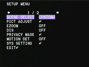
Like all analog video cameras that are really security cameras re-purposed for astronomy, the menu of the R2 can be confusing. But, to get started one really only has to focus on 3 main menu items and ignore all the rest. First is the exposure which has a maximum of 5sec (256X) and steps down by factors of 2 from there, i.e. 2.5sec (128X), 1.25sec (64X) etc. Below 1/25th sec (2X) the exposure settings are shown as 1/50, 1/100, 1/250 … 1/100000. For DSO you will want to stick with exposures somewhere between 64X and 256X. The shortest exposures are useful for planets, the moon and the sun (with appropriate solar filters, or course). To change the exposure select the “Scene Select” menu item "Custom" to get to “Shutter/AGC” where I suggest you start with “Fixed” mode to set both the exposure and the gain. Gain ranges from 6dB to 44dB. In my case, 30 or 36dB seemed to be optimal settings to boost signal without creating a washed out background. Exposure and gain settings will vary with sky conditions, location and telescope so you will have to experiment to find what works best for you. The third setting which is important to take advantage of is the within-camera frame averaging, or DNR. This can be adjusted from 0 to 6 and has the effect of averaging successive frames to smooth out the background and sharpen detail. So, if exposure is set to 5sec and DNR is set to 6, the camera will output an image after 5 sec, but will output an updated and improved image every additional 5 sec. After 30 sec the image will look the same at successive refreshes. If using an Alt-Az mount or a poorly polar aligned equatorial mount, you may not be able to use the maximum DNR and avoid star trailing. Experiment with this also. What do I like best about the R2? 1. The camera is a very good performer, providing some of the best images I have seen from a camera in the $300 or under price range. 2. The included 4.8AmpHour Li Ion battery is small and light weight yet can run both the camera and LCD monitor for 5 hours on a full charge. It will certainly power the camera alone for more than a full night's observing. For $50 you can buy a 9.8AmpHour battery for longer running time. 3. Everything comes neatly packaged with most cables already connected between components to minimize confusion. Just 4. OCT has an excellent reputation for prompt customer service. What do I think could be better? 1. The included battery has fairly short cables which can make it a challenge depending upon where you place the battery relative to the camera and monitor. OCT tells me they have a new battery with a longer power cable. 2. For some, the video cable is shorter than they would like. OCT sells a 25ft power/video cable for $12.99. When I mount everything on top of my SCT, the video cable is actually a bit longer than I need. 3. The LCD monitor is not a high end monitor, so you may want to upgrade to a nicer and larger monitor. You can use your existing television so long as it has a composite video input, which most still do. Is the R2 worthwhile? Absolutely! It is a very well thought out and assembled package. Like I said above, it has everything you need to add to your existing telescope to get started viewing the very first night. Can you buy better accessories than the ones supplied in the package? Certainly, and many prefer to go the route of sourcing the individual components themselves to save some money or to upgrade to better components. But this requires a bit more knowledge of what to buy and how to put it all together. And you will have to purchase many of these components on-line from multiple sellers. OCT has taken all of the hassle and uncertainty out of the process. And their web site has detailed instructions on how to assemble everything, a FAQ section, a guide to the camera menu and suggested starting settings for planetary and DSO objects. In addition, Mike Fowler at OCT has a good reputation for providing telephone support to help get you started. If you are interested in this camera below is a direct link to purchase it online along with the battery and 9" LCD monitor that I use myself. Links are Amazon Associate links. You can also purchase from Orange County Telescope or many other astronomy retailers. Revolution Imager2 |
Categories
All
Archives
January 2024
|

 RSS Feed