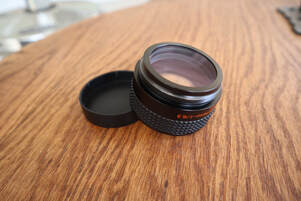
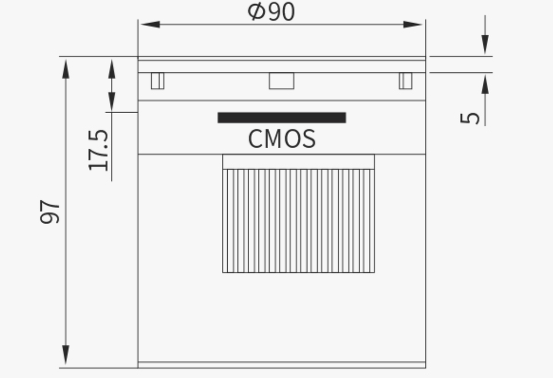
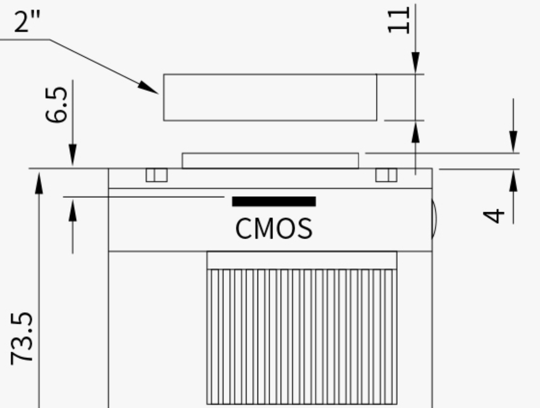
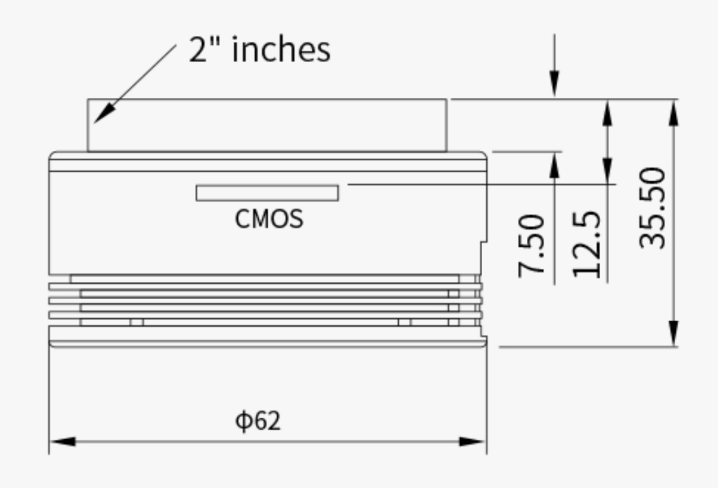
 Celestron's 6.3X focal reducer/field flattener is a very popular accessory for non-Edge SCTs because it reduces the focal ratio of the SCT from its native f/10 to f/6.3. This increases the field of view (FOV) and increases the optical speed of the SCT as well. Both effects are helpful for astrophotography and Electronically Assisted Astronomy as they make shorter exposures possible and allow larger Deep Sky Objects (DSOs) to fit in the camera's sensor. And because it is also a field flattener it will improve the sharpness of the image at the edge of the FOV. The same benefits of a wider field and more intense image apply to visual observers as well Reducing the focal ratio with this reducer speeds up the optics by a factor of (10/6.3)^2 = 2.5. It concomitantly increases the FOV by the same amount. For instance, an 8" SCT with the ZWO ASI533MC camera has a FOV of 19.4 x 19.4 arcminutes at f/10 which increases to 30.8 x 30.8 arcminutes at f/6.3. That is 376 arcminutes-squared vs 949 arcminutes-squared with the later 2.5X the former. For the 8" SCT the focal length reduces from 2000mm to 1260mm with the reducer. Determining the Correct Back Spacing Target For any focal reducer to work as designed It is important to place the sensor of the camera at the correct back spacing, or distance, from the focal reducer. This will ensure that the focal reduction will match the design target, in this case 6.3X. It also ensures that the field flattener works optimally to provide sharp, round stars to the edge of the FOV. If the camera's sensor is placed closer to the focal ratio will be larger, say 6.5X or 7X, and the focal reduction will be less. If it is placed further from the reducer the focal ratio will be smaller, say 6X or 5X, and the reduction will be more. In addition, the field flattener will not perform optimally so stars near the edge of the FOV may be distorted. For astrophotography we want to get the best possible images so we want to be as close to the ideal back spacing as possible. For Electronically Assisted Astronomy (EAA) we may be less fussy about the edge of the FOV and more interested in speeding up the optical system and/or fitting more of the larger DSOs in the FOV. In that case a slightly larger back spacing is sometimes used. Regardless, it is important to know how to get the correct back spacing to begin with. 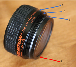 Different locations often identified as the back spacing measurement starting point. 1) Center of the internal lens'; 2) Inner flange; 3) Outer edge of the threads; 4) Back flange. Different locations often identified as the back spacing measurement starting point. 1) Center of the internal lens'; 2) Inner flange; 3) Outer edge of the threads; 4) Back flange. So, how do we achieve the correct back spacing when using the Celestron 6.3X focal reducer? We need to know the correct back spacing and how it is measured. If you search the internet you will find answers ranging from approximately 100mm to 110mm with the most common answer being 105mm. Surprisingly Celestron has not published a spec for the back spacing for this reducer. If you also look to find out where on the focal reducer the back spacing measurement is made, this is where you will find the most disagreement. Some suggest the measurement should be made from the center of the lens' inside the focal reducer (1 in the image above), others from the flat surface on the inside of the threads (2), or the back edge of the threads (3) as shown in the photo. The correct answer to both of these questions is 105mm from the extreme back surface of the focal reducer as shown in the photo identified as location 4 in red. So how do we know that these are correct? 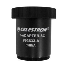 Celestron SCT T-Adapter (50mm) Celestron SCT T-Adapter (50mm) First, we know that the industry standard back spacing for focal reducers used on refractors is 55mm (there are some exceptions). Second, because the optics of an SCT is very different from a refractor it is not possible to make a focal reducer for an SCT with a back spacing of 55mm. So, Celestron did the next best thing. They made an adapter which attaches to the back of the focal reducer and is exactly 50mm long. This leaves the industry standard 55mm left to obtain the correct back spacing of 105mm. Also note that the 50mm length of this adapter is measured from the the flat surface of the flange which mates with the surface "4" in the image above to the flat surface on the other end of the adapter not including the threads where the next spacer will bottom out when screwed all the way on. Similarly, Celestron makes a 7X focal reducer for their Edge SCTs and in this case they do specify the back spacing as 146.05mm. And likewise, they make a T-Adapter to attach directly to this focal reducer which is 91mm long leaving 55.05mm of additional spacing to meet the back spacing spec. So, I think it is clear that the design back spacing for the 6.3X reducer is 105mm and not 100mm, 110mm or something else, and that it is measured from surface 4 on the focal reducer. Imaging Train Options for the 105mm Back Spacing Now that we have established that we need 105mm of spacing for the Celestron 6.3X reducer we need to figure out what options are readily available. But first, we need to take into account the back spacing of the camera sensor itself. This can be found from the manufacturer and we will use ZWO's ASI cameras as an example. Below is ZWO's mechanical drawing for their ASI2600MC camera. This shows the position of the CMOS image sensor relative to the front surface of the camera to be 17.5mm. Likewise the ASI585MC has a back spacing of 17.5mm for the sensor even though it uses a different coupler on the front face. If you look at most cameras these days from ZWO and other manufacturers you will find that 17.5mm is the most common back spacing for the sensor. However, be careful to check as the ASI224MC shown below only has a 12.5mm back spacing. Like plumbing or garden irrigation systems there are many different spacers and adapters available such that one can find many combinations of such to make up the additional back spacing needed. After searching through multiple astronomy supplier's sites I have come up with what I believe to the be the least complicated solutions using the simplest set of adapters available to achieve the 105mm back spacing. I list the parts needed below along with links to either Agena Astro or HighPoint Scientific, two of my goto astronomy suppliers. Links are affiliate links which will earn a small commission at no cost to you. Please use these if you can to support my web site. From Agena Astro Celestron 6.3X focal reducer Celestron 50mm SCT-T Adapter Blue Fireball 37.5mm Extension ZWO 11mm Female to Female Adapter If you want to fine tune the spacing you can use Baader T2 Delrin spacers to adjust the spacing in small increments from 0.6 to 1.4mm. If you want to make larger spacing changes you can search for the desired M42/T2 spacer from Blue Fireball, or substitute the Baader Varilock 46 T2 Variable Extension in place the 37.5mm Extension listed above for greater versatility. Here is an almost identical solution from HighPoint Scientific. Since they do not list a 37.5mm spacer it uses a 30mm and 7.5mm spacer which are sold together as a kit from Celestron. From HighPoint Scientific Celestron 6.3X focal reducer Celestron 50mm SCT-T Adapter Celestron M42 Spacer Kit (30mm + 7.5mm) ZWO M42 Female to Female 11mm Adapter Alternatively to the Celestron M42 spacer kit one could substitute the Baader Varilock 46 T2 Variable Extension which, while almost twice as expensive, allows for variability in the spacing. Also the Baader T2 Delrin Spacer Ring Set is an option for fine tuning the spacing on the order of a mm or less. 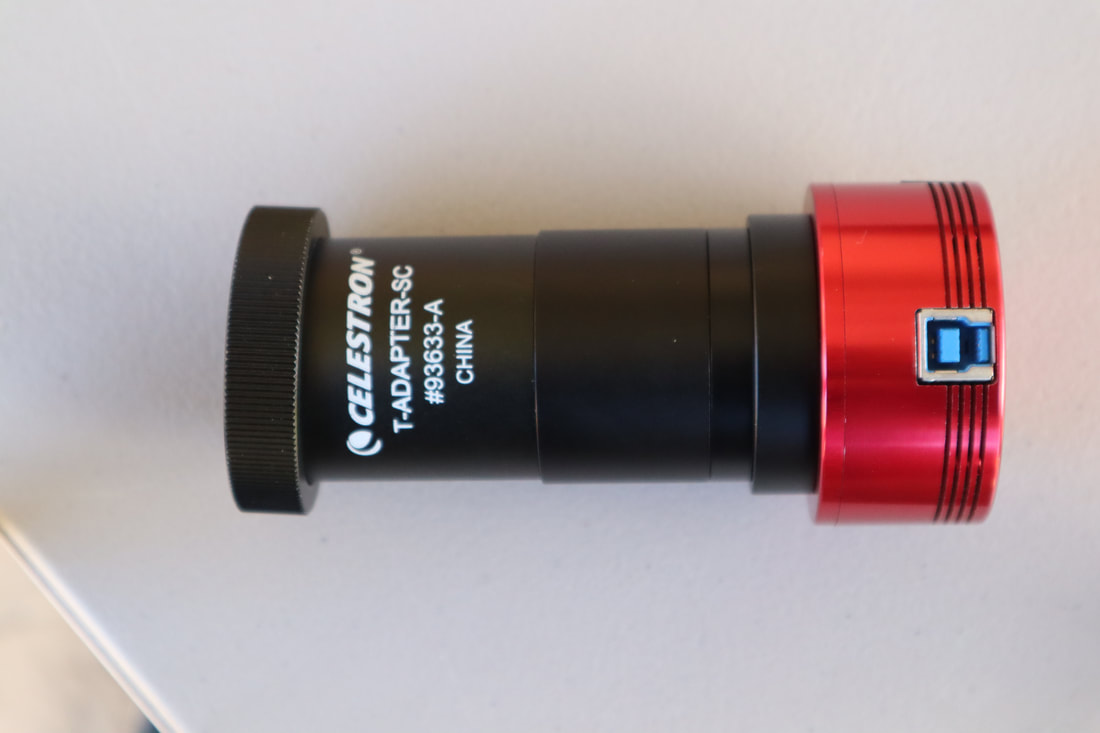 105mm back spacing with ZWO ASI1600MC camera and the adapters/filter listed above from HighPoint Scientific Back Spacing Solutions With a Filter Drawer Now if we want to use filters with our camera we can put a filter drawer in line so that it is easy to change filters in real time. In this case we will need some different spacers and adapters. Also, we need to take into account the fact that the glass of the filter has a different index of refraction compared to air. Filter glass is typically 2-3mm thick so we need to add ~1/3 of that thickness to our optical path for an additional ~1mm. Below is the same setup as above showing the parts needed along with links to either Agena Astro or HighPoint Scientific. Agena Astro Celestron 6.3X focal reducer Celestron SCT-T Adapter Blue Fireball 10mm Extension Blue Fireball 7.5mm Spacer Ring ZWO M42 11mm Female to Female Adapter ZWO Filter Drawer M42 Male to M48 Female ZWO M48 Male to M42 Female Adapter HighPoint Scientific Celestron 6.3X focal reducer Celestron SCT-T Adapter Apertura10mm Extension Baader 7.5mm T-2 Extension ZWO M42 11mm Female to Female Adapter ZWO Filter Drawer M42 Male to M48 Female ZWO M48 Male to M42 Female Adapter 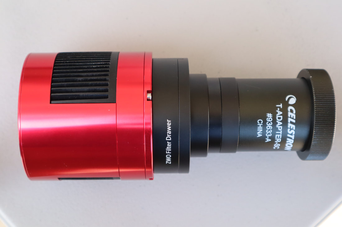 106nm Back spacing with an ASI2600MC camera and ZWP Filter drawer using the adapters/spacers listed in the list from Agena Astro Back Spacing Solutions for SE/Evo/CPC Mounts at 90deg Altitude The solutions above work with cooled and uncooled cameras on any Equatorial mount. In the case of a single arm Alt-Az mount like the Celestron SE or Evolution mounts, or a dual arm mount like the CPC mount, the solutions above will only work as long as the OTA is not pointed higher than ~75 degrees in altitude. Higher altitudes will cause the camera to crash into the base of the mount. A simple solution to reach an altitude of 90degrees without hitting the mount is to add a rail extension along with the imaging trains shown above so that the OTA can be pushed forward to provide enough additional clearance. An inexpensive rail extension is available from SVBony which will work on the 6" SCT. The longer Celestron Universal Mounting Plate is probably a better option for the 8" and 9.25" SCTs and is available from both Agena Astro and HighPoint Scientific. If using a cooled camera there will not be enough room to push the OTA forward and a different approach is needed. This approach uses a diagonal to place the camera at a right angle to the optical axis to gain additional clearance. The details of this configuration can be found in the equipment recommendations section of this web site here. If you would like to see all of these configurations in action, please take a look at the video I put together on this subject where I demonstrate each solution in detail. The video is on my YouTube channel here where you can also find other helpful videos for the amateur astronomer. All links are affiliate links which can earn a commission without any additional cost to you. Please consider using them to help support this channel.
0 Comments
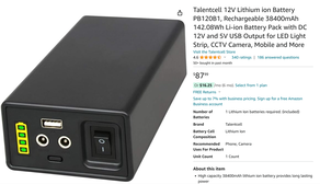 Talentcell sells a line of small and light weight portable power banks which have become very popular among amateur astronomers over the years. Their easy portability means that they can be carried out to a dark sky location or taken to public outreach events to provide limited power without the added burden of a larger capacity battery. It also means that the power bank can be attached to the telescope mount or optical tube to minimize cabling. Advertised on Amazon as 12V batteries Talentcell's power banks are available at prices ranging from $26 for their 3Ah model to $88 for their 12Ah model which can really help to keep the cost of portable power low. One should expect that even the smallest capacity power bank should be enough to power a modest sized mount like a Celestron SE Alt-Az or AVX EQ mount, or a Sky-Watcher Star Adventurer along with a few accessories for several hours. I have used their 8.3Ah model to power a Celestron 6SE along with an analog video camera and 10" LCD when doing EAA at public outreach events. I suspect that hundreds, if not thousands of amateur astronomers have been using these power banks for years completely unaware that they actually are not 12V batteries at all and do not even supply 12V once a load has been applied. I count myself as one so unaware for many years until I started seeing complaints on CloudyNights about problems using these Talentcells to power ASIAIR computers or ZWO AM3 and AM5 mounts all of which had a problem with the actual voltages supplied by the power banks. This prompted me to take a detailed look at the design of the Talentcell power banks. I eventually purchased 3 more Talentcells to run through extensive testing along with my original 8.3Ah model to demonstrate for myself that these are not really 12V batteries and do not provide an output voltage of 12V except when no load is applied. It is important in this discussion to distinguish between the many Talentcell power banks which are advertised as "Lithium ion" or "Li-ion" batteries versus the 2 Talentcell models which are advertised as "LiFePO4 Battery Packs". Of the former I count at least 9 different models being advertised on Amazon as of this writing versus 2 models of the later identified as "LiFePO4 Battery Packs". So what are the differences between these 2 different types? First, the 9 models advertised a "Lithium ion" use LiNiMnCoO2 as the internal power cells. LiNiMnCoO2 (NMC) is a very common Lithium Ion cell used in many applications, primarily where weight is a key concern such as in ebikes, electric power tools, some models of electric cars including many models of the Tesla, and in most of the portable power stations like the Jackery sold to date. NMC is considered one of the safest Lithium cells with a thermal runaway temperature second only to LiFePO4. Power supplies with NMC cells are usually rated for ~500 full discharge cycles after which 75 - 80% of the original capacity remains. In contrast power supplies with LiFePO4 are rated at 4,000 or more full discharge cycles which is why these are found in the batteries used in RVs and boats. LiFePO4 cells are now beginning to show up in portable power stations from Jackery and others. 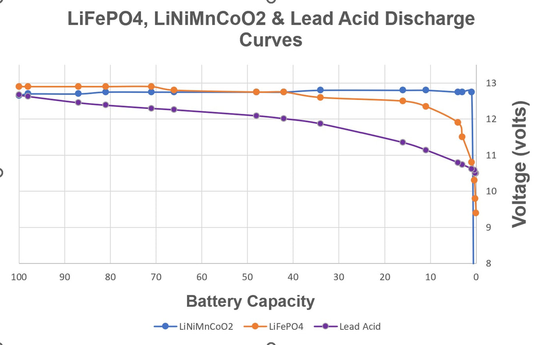 The other main difference between NMC and LiFePO4 cells, and one of the keys to understanding the problem with many of the Talentcell power banks, is their nominal cell voltages. NMC has a nominal cell voltage of 3.6 to 3.7V. That means when fully charged it has a useable energy capacity starting at 3.6 or 3.7V. On the other hand, LiFePO4 has a nominal cell voltage of 3.2V which actually makes it an ideal lithium cell type for creating a 12V battery as 4 of the LiFePO4 cells in series will provide 12.8V. On the other had, 4 NMC cells in series will provide 14.4 to 14.8V which is too high for a typical 12V system. This is why a Jackery portable power stations using NMC cells have an internal voltage regulator to keep the output voltage in the 12V to 13.2V range throughout 100% of its depth of discharge (DOD) at which point the internal BMS shuts down the output. In contrast, a 12V battery using LiFePO4 cells does not need a voltage regulator so its voltage remains above 12.0V throughout 95% of its DOD. The voltage versus capacity curves shown above for LiFePO4, LiNiMnCoO2 and a lead acid battery demonstrate this quite clearly. 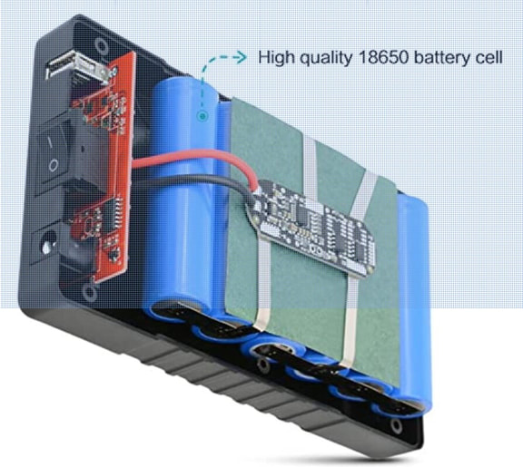 Tanlentcell 6Ah power bank 3S2P design with 2 banks in parallel of 3 NMC cells in series 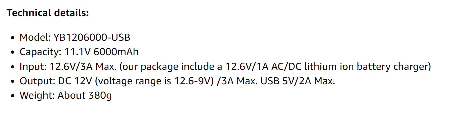 Talentcell 12V/6000mAh technical specs Talentcell 12V/6000mAh technical specs So why do I say that the Talentcell power banks using NMC cells are not 12V batteries? To understand this we need to take a look at the design of these power banks. Here we have Talentcell's own advertised design information which shows that they are using 3, not 4, NMC cells in series and then adding multiples of these in parallel to increase the capacity as needed. Here is an image of their 6Ah design which has 6 total cells configured as 2 parallel banks of 3 cells in series. The 3 cells in series can only produce 3 x 3.7V = 11.1V , not 12.8V. Interestingly, if you look closely at Talentcell's own specifications you will see that they indicate 11.1V 6000mAh for the capacity in the technical details for this battery, not 12V 6000mAh. (6000mAh is 6Ah). Yet, looking into the technical details you will see the output rated at a voltage range of 12.6V-9V. So where do they get 12.6V from? Well, let's take a look at the discharge curve for a LiNiMnCoO2 cell from Panasonic. These curves are for different discharge currents but each shows that while the cell can be charged to as much a 4.2V, the voltage drops below 4.0V, even to 3.7V depending upon the discharge current, as soon as a load is applied. With no load applied, 3 cells at 4.2V will show a voltage of 12.6V which is what the Talentcell spec is referencing. But with even a small load the voltage drops immediately below 12V because there is essentially no capacity in the cell above 3.7V. 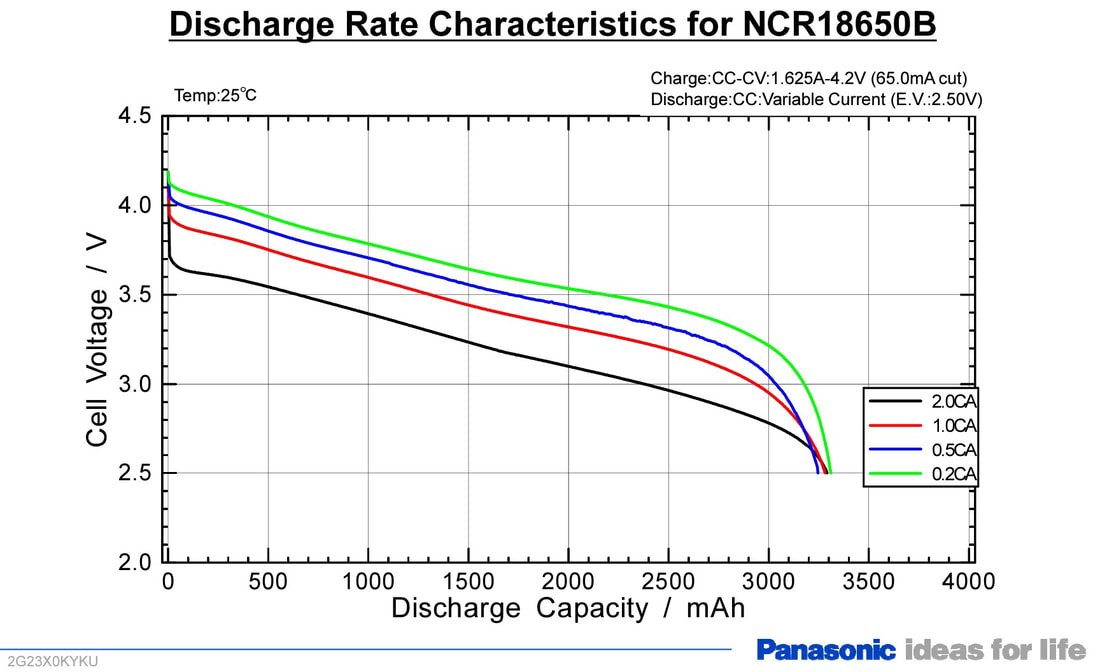 Voltage versus capacity for LiNiMnCoO2 cells from Panasonic 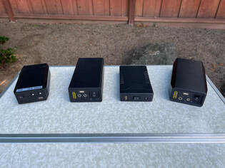 My original 8.3Ah Talentcell along with a 12.8Ah and 6Ah model and a 6.5Ah LiFePO4 model. My original 8.3Ah Talentcell along with a 12.8Ah and 6Ah model and a 6.5Ah LiFePO4 model. To confirm all of this I purchased 2 of the power banks utilizing the 3S design with NMC cells, a 6Ah and a 12.8Ah version added to the 8.3Ah version I already had. I also purchased a 6.5Ah Talentcell power bank using 4 LiFePO4 cells in series for comparison. I ran each of these through a full discharge cycle test after first fully charging them per the manufacturer's instructions. 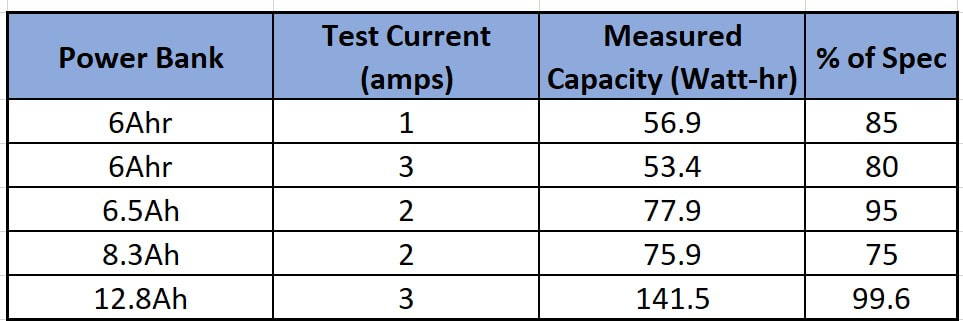 The measured capacities for each power bank are shown in the accompanying table. I used a load current at least half the rated current for each power bank in the capacity test to avoid stressing the battery. In the case of the 6Ah power bank I also used the maximum rated current of 3A to see if the measured capacity differed. Only the power bank with the 4S design using LiFePO4 cells met the rated capacity while the other 2 new power banks fell short by 5 and 15% respectively. I did not expect my 6 year old 8.3Ah power bank to match the rated capacity since I did not care for it well over its lifetime. More important than the rated capacities is the voltage versus capacity curves which are shown in the graph below. There are two curves for the 6Ah power bank since I measured this at both 1A and 3A loads. The curves show that while the no load voltage is 12.6V per the spec, the voltage drops below 12.0V as soon as a load is applied. For all 3 power banks the voltage drops below 11V with 70% of their rated capacity left which is quite amazing for a battery sold as a 12V battery. While lots of 12V equipment, including our typical astronomy gear, has a wide voltage tolerance, they are not designed to operate optimally when the voltage drops this low. This is clearly why the ZWO ASIAIR and AM3 and AM5 do not like these power banks. Even more amazing is the fact that these batteries drop below 10V with 30% of their capacity remaining. Even if your equipment works down to 10V, you are not getting the capacity you are paying for with these power banks. Looking at the 3A load curve for the 6Ah battery we can see if we push to the maximum current of the power bank the voltage drops even more precipitously and we can expect our equipment to quit or, at least, complain much sooner. 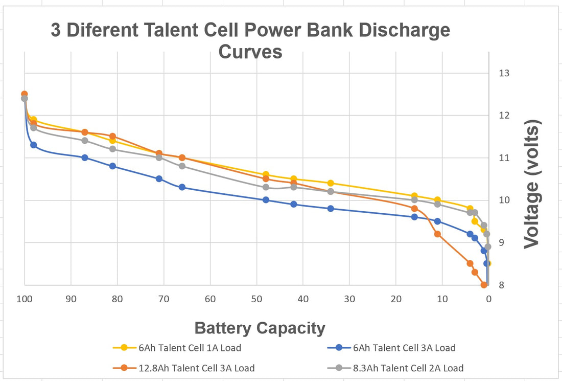 So, why is this happening? Well I can only guess as to the reason that Talentcell uses a 3S design with these 9 different 12V power banks. First, with less cells they save space and weight which helps to keep the power banks small and portable which is their main selling feature. Also, by not using a 4S design they save on the cost of additional cells and the cost of the voltage regulator that would be required to drop the voltage into a typical 12V power supply range. It is the simple fact that they use 3 cells in series and not 4 with a voltage regulator that these are not really 12V power banks. On the other hand, the 4S designs with LiFePO4 perform perfectly as expected for a 12V battery and are the only ones that I recommend. As the voltage versus capacity curve below shows, the voltage stays above 12V for about 90% of its rated capacity with a load of 2A which is ~36W of power. If you push the power bank to its maximum current capacity of 5A the voltage drops more quickly but stays above 12V for ~66% of capacity and doesn't drop below 11V for 95% of the total capacity. Talentcell currently has one 4S model which uses LiFePO4 cells and has a capacity of 6.5Ah, which is model that I bought and tested and which be can found here. And if you need more capacity than that, here is a 12Ah LiFePO4 battery from Talentcell which is not a power bank but is still small enough to fit in the palm of a hand. ( Links are affiliate links). 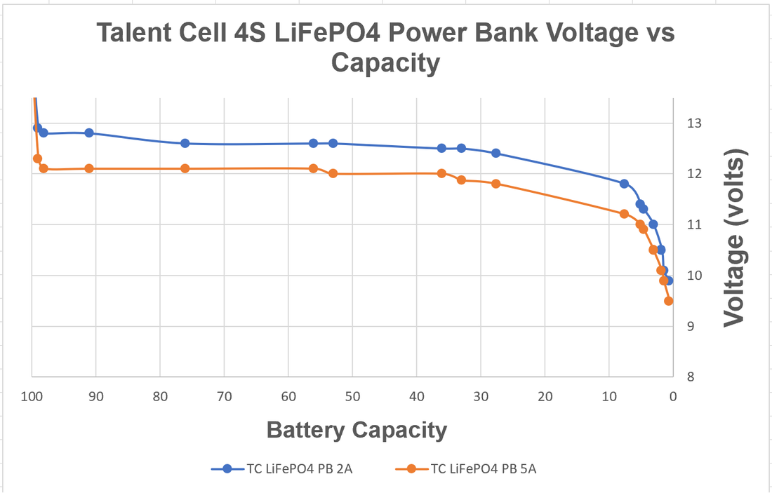 Talentcell is not the only one using a 3S design in their "12V" batteries. A short survey on Amazon found several other manufacturer's of power banks doing the same thing. And, amazingly to me, I found that even some of the portable power stations available such as the EBL 300Wh model specifies a DC output voltage of 9 - 12.6V just like the Talentcells with a 3S design while the EBL models 500 and 100 (which I tested and reported on here) specify a DC output voltage of 11.8 to 14V which is consistent with a 4S design with NMC cells and a voltage regulator. So my suggestion is to look carefully at the specifications before you buy.
If you want to see more on this topic, I made of video showing exactly how I tested the 4 Talentcell power banks which I bought and which you can find on my Youtube channel. These are the only TalentCell power banks that I would recommend, along with a 12Ah LiFePO4 battery if you need more power. Links are affiliate links which can earn a commission without any cost to you and help support this web site. Talentcell 12V LiFePO4 Battery 12.8V 6.5Ah 83.2Wh - amzn.to/3NYIPxD Talentcell 12V LiFePO4 Battery 153.6Wh 12.8V 12Ah: amzn.to/3SfDMM0 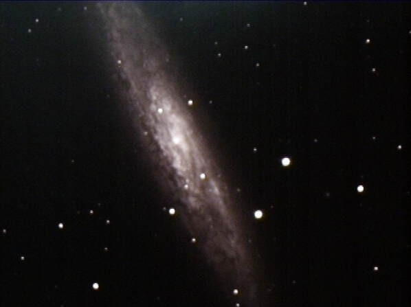 22 sec image of NGC253 Hyperstar on a 14" SCT 22 sec image of NGC253 Hyperstar on a 14" SCT If you own a Celestron SCT and do not already have a hyperstar adapter you should. What is hyperstar? It is a multi-element optical adapter which converts the focal ratio of an SCT from its native f/10 to f/2. Since the optical speed of a telescope is proportional to the square of its f-ratio, adding a hyperstar will increase the speed of an SCT by a factor of 25: speed ~ (10/2)^2 = 5^2 = 25. My first experience with hyperstar was back in 2015 when I first tried it on my 14" SCT to capture a breathtaking view of NGC253 the Sculptor Galaxy in just 22seconds. I was just blown away by what the hyperstar was able to capture in such a short time. Of course, smaller aperture telescopes will not produce such an image in the same time, but they will still have 25X faster optics resulting in amazing images in short times of their own right. Hyperstar is available for the 6", 8", 11" and 14" Celestron Edge and non-Edge SCTs and the 9.25" Edge version. It has been available for these models for some time. Just check the front of the Secondary mirror for the phrase "Fastar", where Fastar is the original Celestron name for this, to see if your older model is compatible. For those that do not say "Fastar" a conversion kit is available for all 6" through 14" models except the 9.25" model. 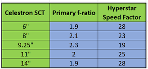 How does hyperstar work? An SCT consists of three optical elements, a corrector plate at the front, the primary mirror in the back and the secondary mirror in the center of the corrector. SCT primaries are spherical mirrors configured to a focal ratio of f/2. Actually the focal ratio of a Celestron SCT primary varies between f/1.9 and f/2.3 depending upon the model as shown in the accompanying table. For the sake of simplicity, lets stick with f/2 as our example. The secondary mirror is figured to a focal ratio of f/5 so the combined effect is a focal ratio of f/10, f/2 x f/5 = f/10. 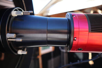 The camera adapter is seen between the hyperstar and the camera. The camera adapter is seen between the hyperstar and the camera. Hyperstar is installed by removing the secondary mirror and replacing it with the hyperstar compound lens. With no secondary the focal ratio is that of the primary mirror, or f/2. Obviously the hyperstar element can only be used with a camera for imaging, either for traditional astrophotography or electronically assisted astronomy, and not for visual observations. A camera is attached to the hyperstar via an adapter which is specific to the camera and hyperstar size. The light enters the SCT through the front corrector plate and reflects off the primary mirror just as it always does. But now, instead of reflecting off the secondary mirror back through the center of the primary and out the back of the SCT, it travels through the optical elements of the hyperstar and into the camera. The hyperstar is a multi-element lens/corrector which not only focuses the light onto the sensor in the camera, but also corrects for the spherical aberrations and field curvature which would be present without the corrective capability of the hyperstar. Images taken with the hyperstar should be sharp and flat across the field of view. Hyperstar can be used for both traditional astrophotography and electronically assisted astronomy. In both cases, the faster focal ratio enables more light to be collected in a given time compared to the SCT's native focal ratio of f/10. The results can be stunning as in the traditional astro photo of M31 shown below taken on a C11 with hyperstar for a total exposure time of 213 minutes using Pixinsight to combine and process hundreds of sub-frames. Similarly, amazing results can be obtained during live stacking and viewing during an EAA session as seen in the image of the Rosette Nebula taken with TSX's Live Stack feature stacking and stretching 120 x 5 sec sub-frames for a total of 10 minutes also using a C11 with hyperstar. 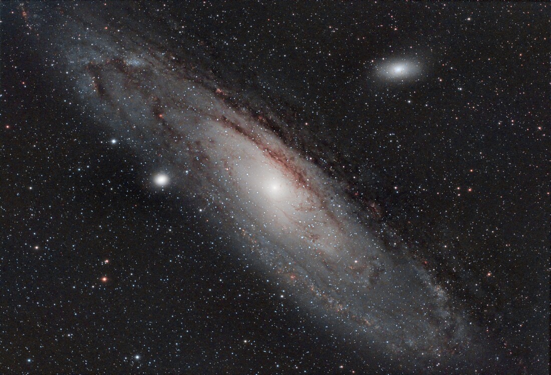 Traditional astrophoto of M31 taken with Hyperstar on a C11 with an ASI294MC Pro Camera 213min stack  Live stack image of the Rosette Nebula taken with Hyperstar on a C11 with an ASI2600MC Pro camera with a total stacking time of 10min 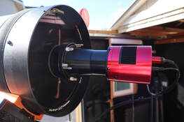 A C11 with hyperstar and an ASI2600MC A C11 with hyperstar and an ASI2600MC Installing Hyperstar Removing the secondary mirror from your SCT may sound scary but it really is a simple matter. I like to set the OTA at a slightly elevated angle so it is easy to reach the secondary and gravity will still help to keep it in place when its retaining ring is removed. The secondary slides out and can be placed into the protective holder which comes with the hyperstar. The hyperstar is threaded onto the secondary holder. But be careful not to over tighten the hyperstar. Finger tight is sufficient. I once got the hyperstar so tight that I had to remove the corrector plate to get it back off. You should not have this problem if you do not over tighten the hyperstar like I once did. After installing the hyperstar several times you will even feel comfortable doing this in the dark. The procedure should take only 5min or less. While hyperstar can weight as much as 3lbs for the 14" SCT it is not going to damage your corrector plate when handled carefully. An SCT corrector plate is much stronger than one may realize. Still, I would never transport an SCT with a hyperstar installed as the possibility of banging into the hyperstar is always present. Also, when covering the telescope using a hyperstar with an all weather cover just be careful that the cover does not snag on the hyperstar which protrudes from the OTA. I leave my hyperstar on for multiple days while in the field using a dew shield and cover over the hyperstar and correct which keeps dirt and dust off the corrector. At home I leave my hyperstar mounted on my SCT in the backyard observatory as long as I plan to work at f/2. There is really no need to remove and re-install hyperstar every day. 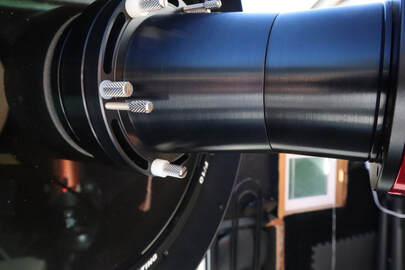 Push/Pull collimation pins at left and a rotation thumbscrew at bottom Push/Pull collimation pins at left and a rotation thumbscrew at bottom Hyperstar Collimation Just like the secondary mirror on an SCT, hyperstar will need to be collimated from time to time. Fortunately, hyperstar seems to hold collimation just as well as a secondary mirror so you should not expect to need to collimate any more frequently than you do without it. Also, you most likely will not need to re-collimate your scope when you put the secondary back since it is indexed to the optical axis with a pin which fits into a notch in the flange which holds the secondary. Hyperstar has 3 sets of push/pull pins located at 120 deg increments around the outside for the purpose of collimation. There are two strategies for initial collimation. The simplest takes advantage of the high precession machining of the two hyperstar mechanical bodies. Just adjust the push/pull pins so that both flanges of the hyperstar bodies are in contact all the way around and then tighten the pins. So long as these two flanges are parallel to one another and the corrector plate is aligned with the primary mirror you should have good collimation. Several folks have reported that this has worked for them so it is worth trying first. If you are not satisfied with the collimation with that approach you can use the second method. With this approach you will need 3 shims 30 to 40 mil thick. Metal stock of this type can be found at your local Ace hardware or online. I use Cu stock which I cut into 3 pieces long enough to fit between the two hyperstar flanges. With the shims spaced 120 degrees apart between the two hyperstar flanges, tighten the push/pull pins just enough so that you can barely pull the shims out. Make sure that you tighten pins are engaged so that the flanges do not come loose. Then, under the stars perform a collimation as you normally would using the push/pull pins in the same way as you would the 3 screws on the back of the secondary mirror. You will find that it is a lot easier to adjust the push/pull pins with your fingers. Just make sure they are all tight when you are satisfied with collimation. A very large variety of cameras are compatible with hyperstar including those from ZWO, QHY, ATIK, SBIG, etc. When ordering the hyperstar element you will need to specify the camera that you will use with it since a camera adapter is required to attach the camera to the hyperstar lens at the optimum distance from the camera sensor.  Hyperstar filter drawer and slider Hyperstar filter drawer and slider Using Hyperstar The hyperstar adapter has 3 thumbscrews which are designed to allow 360 degree rotation of the hyperstar so that you can adjust the orientation of your camera. Just loosen all three thumbscrews 1/4 turn, rotate the the outer body of the hyperstar to the desired orientation of the camera. Then tighten the thumbscrews to lock the camera orientation. Since these thumbscrews hold the two halves of the hyperstar together, you should never completely remove them. USB and power (if needed) cables are attached to the camera as usual. If you are using a dew shield you can either bring the cables out the front of the shield or, out the back of the shield if it has a notch in it. In either case tie off the cables so they do not drag. In some cases, the cables may produce diffraction spikes on bright stars just like the spider vanes on a Newtonian secondary. This can be minimized by avoiding running the cables in a straight line across the front of the OTA. The hyperstar camera adapter is threaded inside so that a filter can be attached. This works well if you intend to use only a single filter, such as a light pollution filter, a UV-IR filter or a multi-band filter during you imaging session. Just unscrew the front piece on the adapter, screw in the filter and screw the adapter/filter combination back on. Then attach the camera. If you want to change filters during a session you will need a filter drawer for the hyperstar. The filter drawer screws onto a separate hyperstar adapter such that the combination provides the correct backspacing for your camera. Everything else in an imaging or EAA session will be the same as if you did not have the hyperstar except it will require much less time to be able to see DSOs compared to operating at f/10. Wide Field Since the hyperstar reduces the focal ratio to f/2 but does not reduce the aperture of the telescope, the field of view will be much wider. In fact, the field of view will also be 25X larger compared to f/10, 5X in each axis of the camera sensor. This is precisely how the hyperstar speeds up imaging. To understand this let's take a look at the difference in image scales at f/10 and f/2. Image scale depends upon the size of the pixels in the camera and the focal length of the telescope. It is defined by the following equation: Image Scale (arc-sec/pixel) = 205 x pixel size (microns) / focal length (mm) So, for the same camera, the image scale varies inversely with the focal length. In other words, the image scale increases as the focal length gets smaller. Adding the hyperstar reduces the focal length proportional to the reduction in focal ratio. For the C11 discussed above the focal length is reduced from its native 2794mm to 559mm with hyperstar. The image scale is then reduced by the same factor of 5 across the x and y axis of the camera chip. This means that each pixel is collecting light from an area of the sky 25X larger with the hyperstar than without the hyperstar which is why the exposure time is reduced. Keep in mind that with the wider field of view the resolution is now reduced by the same amount. But since seeing conditions usually dominate image resolution stars and most CMOS cameras used for astronomy have sensors with pixels smaller than 4microns on a side the image quality will still be excellent, even if you zoom in on the image. Summary
Hyperstar is certainly expensive costing just under $1000 for an 8" SCT and more for larger apertures. However it should be viewed as turning your f/10 SCT into a completely new telescope with a focal ratio at least 4X faster than the fastest refractors available while maintaining an aperture many times larger than a refractor. Think of it as investing in an entirely new scope but without having to purchase a new set of accessories (finder, dew heater, focuser, etc.). As the few images shared here show, hyperstar can produce incredible images in real time and is well suited to capturing more of the larger DSOs. If you want to see more about the amazing hyperstar check out my hyperstar YouTube video Links are affiliate links which can earn a commission without any cost to you. Please consider using them to help support this web site. Hyperstar is available from HighPoint Scientific bit.ly/3RO8vgv  Jackery Solar Saga 100, EBL Apollo 100 and Bioenno Power 100W Solar Panels Jackery Solar Saga 100, EBL Apollo 100 and Bioenno Power 100W Solar Panels I have previously reported on my results testing several different portable power stations from Jackery, EBL and Bluetti along with LIFePO4 batteries from Li Time (formerly Ampere Time), Bioenno Power and Battleborn to power my astronomy rig out in the field. Typically we travel to distant dark sites for multiple nights under the stars and most likely will need some way to recharge a power station or battery during the day. Portable solar panels are a great way to do this when AC power is not available. So in this blog I will review three 100W portable solar panels that I have been using over the last few years. While the panels were sent to me by their suppliers at no cost to me I am under no obligation to provide a positive review and/or avoid negative comments if they are warranted. None of the suppliers has seen this review before it was posted. So here we go. The three solar panels are the Jackery Solar Saga 100, the EBL Solar Apollo 100 and a 100W panel from Bioenno Power. Each is designed for a maximum of 100W of output power, but anyone already familiar with solar panels know that the 100W specification is only achieved under ideal laboratory conditions with a well controlled and uniform light intensity at the optimum angle and at room temperature. In real world conditions, expect to get ~70 to 90% of the specified maximum rating out of any solar panel. All 3 of the panels in this review use monocyrstalline silicon photo voltaic chips which are the most efficient solar panels on the market with an efficiency of 24%.  Jackery Solar Saga 100 The Jackery Solar Saga 100 is highly rated but is one of the more expensive panels at $269 as of this blog. The Jackery has an output voltage of 18V at 5.55A which works out to 99.9W. The panel is fairly large with an unfolded dimension of 48" x 21". When folded it reduces to 24" x 21" and 2" thick which makes it fairly easy to pack away for travel. It has convenient built in carrying handles and magnets to help keep the two halves together when closed. Jackery claims that the panel weighs only 5.5lbs but I measured it to actually be 9lbs, which is considerably more but not difficult to carry around. A big plus of the Jackery compared to the other panels is the two large, 6.25" wide, kickstands which make it easy to set up and keep both halves of the panel at the same angle to the sun. The panel is coated with a plastic material to make it more durable and easier to clean and is splash resistant but not waterproof. I found the overall build quality to be quite good and the panels (I have 2 of them) have stood up quite well to occasional use over the last 2+ years. The electrical connection is inside a zippered case and includes a single 10ft long 16AWG cable with an 8MM male plug designed to be plug compatible with Jackery's portable power stations. If you have another brand of power station which does not use the 8mm connection you can get an adapter to connect the Jackery panel to it. I like the fact that they provide a long cable which allows flexibility in positioning he power station or battery being charged. It is best to keep the power station or battery from direct sun exposure and I typically place it behind the panel. I also like the fact that the input cable is strain relieved at the point that it connects to the panel. There are two USB ports ( 5V/3A USBC 5V/2.4A USBA) at the strain relief which allow direct charging of USB devices by the panel such as your phone, laptop, tablet, camera, etc. The Jackery solar panel comes with a 2 year warranty and technical support is available in Fremont, California so you do not have to email China for help. I will note that one of the 2 Jackery panels sent to me did fail after about 1 year of use for no apparent reason and was promptly replaced with a new panel.  EBL Solar Apollo While EBL is not as well known of a brand in the power station and solar panel business, it has been around since the 90s as a manufacturer of alkaline, NiCd and other types of batteries and chargers. A major appeal of the EBL Solar Apollo 100 is that it is one of the least expensive 100W panels at $149 which is almost half the price of the Jackery. The output voltage of the EBL panel is 20V at 5A which works out to 100W. The EBL is about 23% larger than the Jackery when fully open with an unfolded dimension of 46' x 26.75". It is only slightly larger than the Jackery when folded with a dimension of 26.75 x 23 but that still makes it less convenient to pack for travel compared to the Jackery. It also has convenient built in carrying handles and magnets to help keep the two halves together when closed. The EBL panel weighs 9.5lbs. I wish EBL had made the two kickstands wider like the Jackery as theirs are only 4.25" wide which makes it a little bit harder to support given the larger overall dimensions of the panel. This panel is also coated with a plastic material to make it more durable and easier to clean and is splash resistant but not waterproof. Just like the Jackery the EBL has a zippered pouch which houses the output cables connected to the panel. However, the EBL panel uses a pair of 3ft cables with MC4 connectors on the ends. I found the short cables to be stiff and therefore difficult to manipulate. But they do supply two additional flexible adapter cables, one which converts from the MC4 connectors to a Power Pole connector and the other to a 5.5mm x 2.1mm connector. Plus they include 5.5mm x 2.1mm to 8mm, 5.5mm x 2.1mm to 5.5mm x 2.5mm, and 5.5mm x 2.1mm to 3.5mm x 1.5mm adapters so that the Apollo panel can be connected to pretty much any brand of portable power station. Unlike the Jackery, the Solar Apollo panel does not have a USB charging port. But much more importantly it does not have a rigid strain relief where the cable connects internally to the panel like the Jackery. Instead there is a simple loop which was not enough to prevent one of the cables on the panel from partially coming out of its internal connection exposing a bare lead. The panel comes with a 1 year warranty and technical support is available only through China.  Bioenno Power The Bioenno Power solar panel is designed very differently from the other two panels. It is a quad -fold panel which means that it folds down to a much smaller package measuring 20.5" x 14.5" which makes it easier than either of the other two panels to pack in a smaller space. Unfolder it is the longest of the panels at 57" x 20.5". I found the two 2" wide kickstands totally inadequate to set up the panel so that all four segments are aligned in the same plane. This would be much better if that had 3 or 4 kickstands at least 3" wide. It also has a convenient carrying handle and clips to hold the panel shut. The Bioenno panel weights slightly more than the other two at 10lbs. This panel is priced between the other two at $210 and it has an output voltage of 18V with 5.56A. Just like the other two panels the cable sits inside a zippered compartment. Unfortunately, the cable is even shorter than the one provided by EBL which means that you will definitely need to buy an extension cable to have any practical chance to connect the panel to a power station. But, since the Bioenno Power uses a non-standard 50A Anderson Power Pole connector you would certainly need an adapter cable anyway. Bioenno Power sells an adapter cable which converts to the much more common 40A Anderson Power Pole connector. Like the EBL the Bioenno Power does not have a USB charging port but does have a solid strain relief like the Jackery . 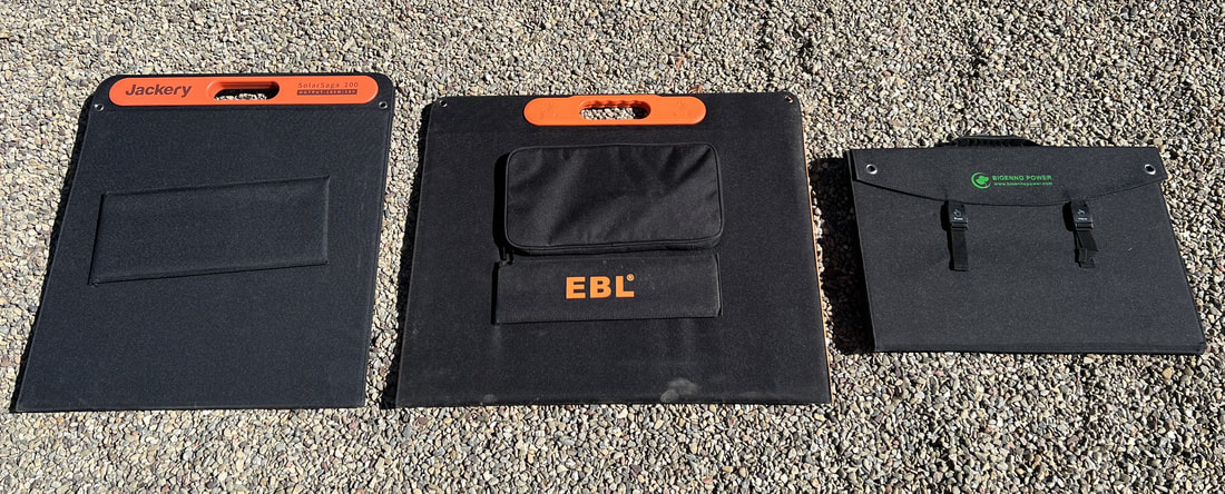 All 3 panels folder for travel showing relative sizes 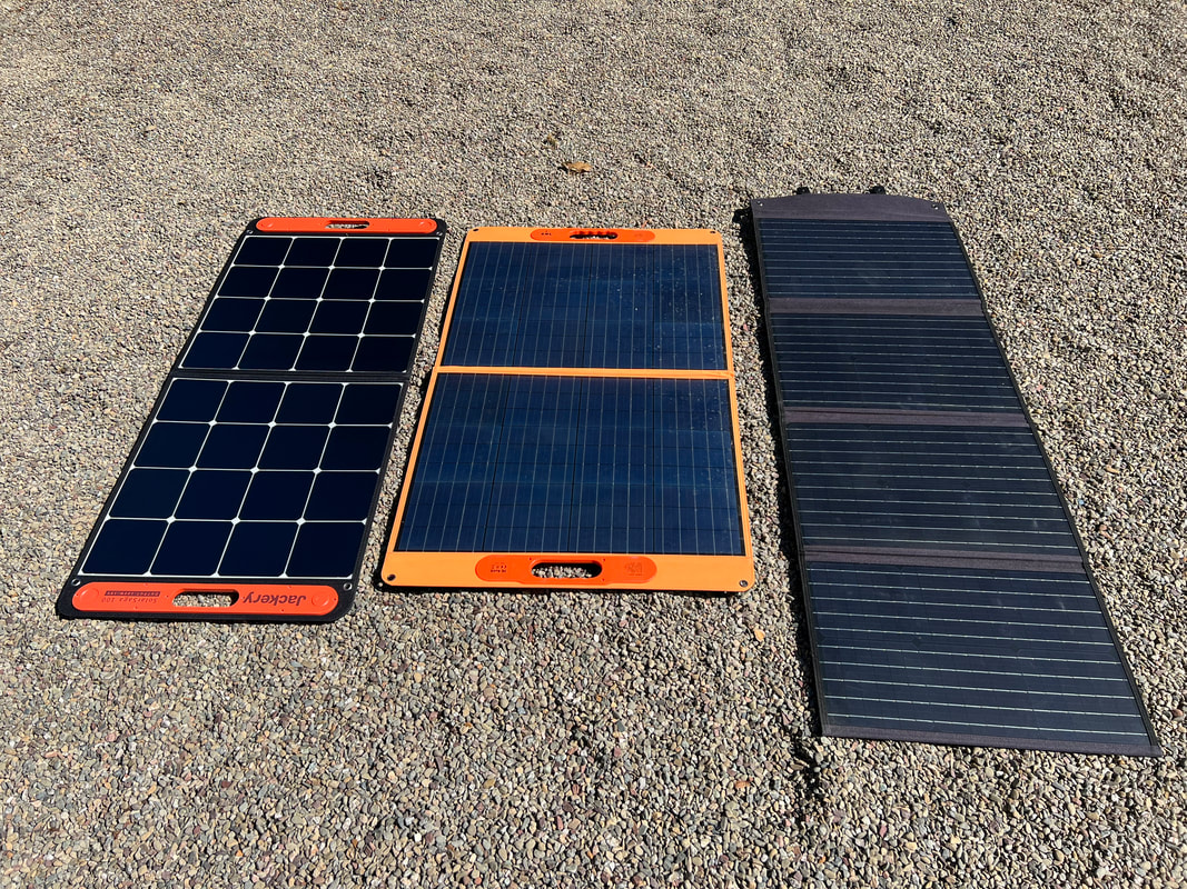 All 3 panels open showing their differences in length and widths 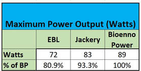 Charging Tests I performed two different charging tests on each panel. The first test was designed to determine the maximum output power of each panel on a clear sunny day in June with the sun at its peak in the sky for the day. Each panel was supported by a piece of plywood to hold it flat in a plane and tilted in altitude and rotated in zenith relative the the sun until a maxim input reading was obtained on a Jackery 1000 portable power station's input meter. The Bioenno Power produced the highest maximum output of 89W, while the Jackery had a maximum of 83W and the EBL panel produced the lowest power output of 72W. As discussed in the beginning we see clearly that the outputs are not 100W. The Bioenno Power panel outperformed the other two with the outputs of the Jackery at ~93% and the EBL at only ~81% of the Bioenno Power's output. 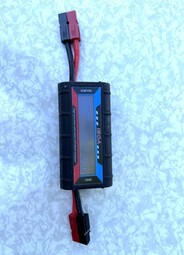 The next test was a 3 hours cumulative power output test. Here I measured the output power produced over a 3 hour period on a clear sunny day in June starting 1.5 hours before the sun peaked in altitude through 1.5hrs after the peak. Thus the panels were exposed to the maximum solar radiation possible on that day. To measure the output power I used identical in-line DC power meters which measure the power, voltage, current, Ah and Wh produced. I needed something for the solar panels to charge during the tests but I did not have 3 identical power stations which would have made the test very simple. Instead, I used my Jackery 1000 and EBL 1000 portable power stations as the loads with the DC power meters between the panels and the power stations. Since the charging circuits on the two power stations may behave differently I had each panel charge each of the two power stations for half the 3 hour time so as to accommodate any variation in power because of differences in the power stations. So each panel charged each power station for 1.5hrs during the test. Now, 3 panels into 2 power stations does not divide evenly. So, I ran the test in pairs, testing all three combinations of pairs over 3 days with clear skies from 11:30AM until 2:30PM swapping power stations and in-line meters at the midpoint of 1PM. Test Order: Day 1: Jackery Solar Saga vs. EBL Apollo Day 2 EBL vs Bioenno Power Day 3 Jackery vs. Bioenno Power 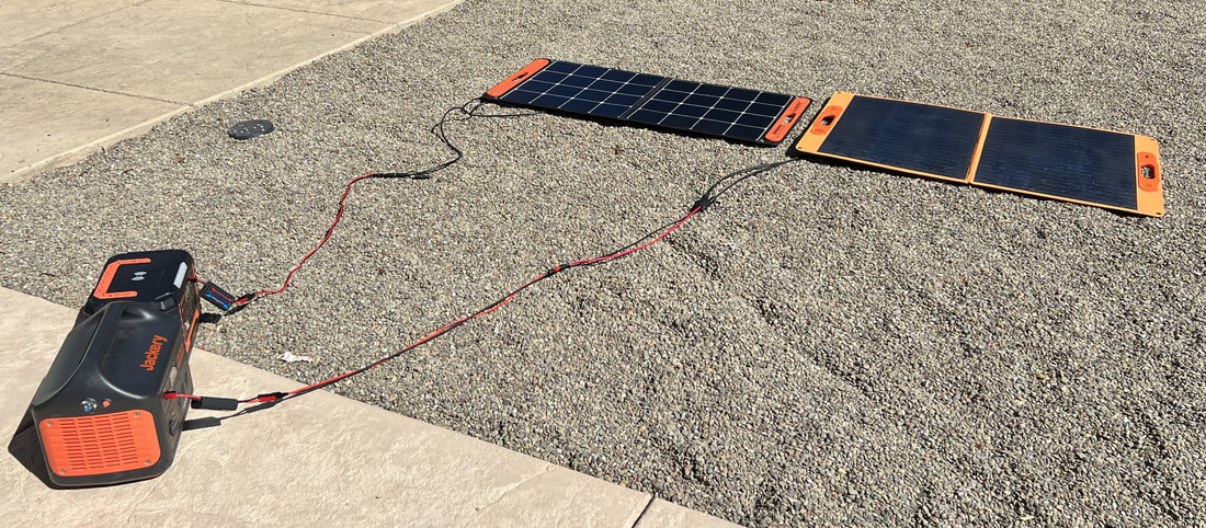 Jackery & EBL Panels in the 3 hr test connected to the EBL 1000 and Jackery 1000 portable power stations through identical in-line DC meters The results are shared in Table 2 below which shows that the Jackery produced 35Wh, or 16%, more energy than the EBL Apollo over the 3 hours on day 1. The Bioenno Power panel produced 32.5Wh, or 18%, more energy on day 2 than the EBL panel. And on day 3 the Bioenno Power Panel produced 9.7Wh, or 6%, more energy than the Jackery solar panel. 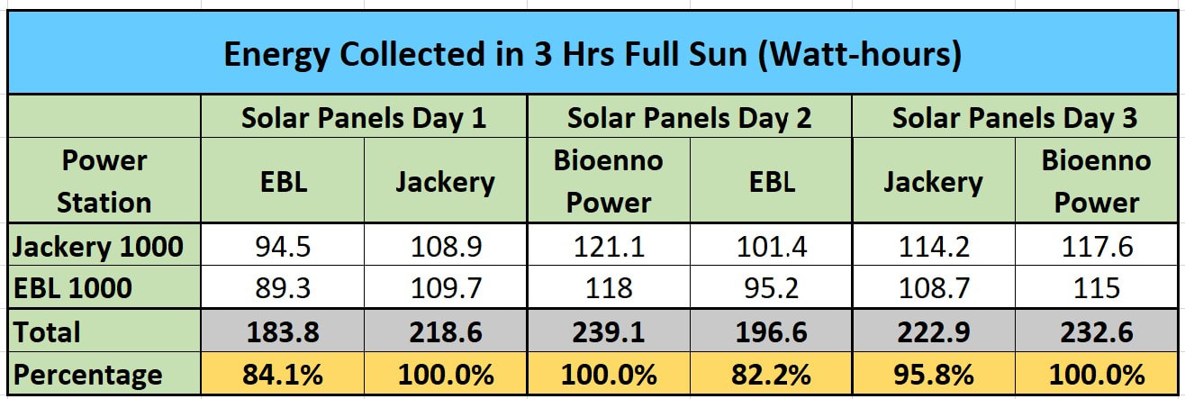 Table 1. Raw data collected for each solar panel/portable power station combination by Day. 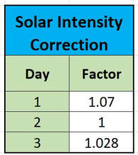 Table 2. Solar Correction Factors Table 2. Solar Correction Factors Now, to be fair, even though the measurements were done at the same times on all 3 days, and even though all 3 days were clear sunny days, we cannot be certain that the flux of photons was the same each day. But there is a way to correct for any differences in the amount of solar radiation over the 3 days. We can normalize the numbers to the one of the panels on one of the days, in this case, the Bioenno Power output on Day 2. Since we have each panel tested on 2 days we can take advantage of the readings on the same panel from day to day to correct for differences in solar radiation. If we take the ratio of the Bioenno Power reading on Day 2 to Day 3 we get 121.1 / 117.6 = 1.03, which means that the solar radiation on Day 2 was 3% higher than on Day 3. Next we can scale the EBL measurements from Day 2 and Day 1 to get 101.4 / 94.5 = 1.07 which shows that the solar radiation on Day 2 was 7% higher than on Day 1. Using these Solar Intensity Correction factors we can scale the Day 1 and Day 3 readings to the readings on Day 2 using 1.07 to scale Day 1 and 1.03 to Scale Day 3 as shown in Table 2. 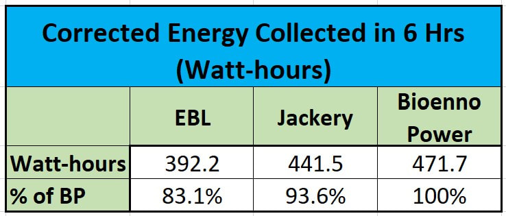 Table 3. Energy Output of each solar panel over 2 days (6hrs) corrected for day to day solar radiance differences Table 3. Energy Output of each solar panel over 2 days (6hrs) corrected for day to day solar radiance differences The result is the corrected Table 3 shown below. This shows that the panels collected a total of 392 to 471 Watt-hours of energy over a 6 hour period of peak solar intensity. The Bioenno Power panel collected the most energy at 471Wh. If the panel had actually output 100W during those 6 hours we would have expected 600Wh of energy. Instead, we got 78.5% of the ideal expectation. Now keep in mind, the panels lay flat on the ground so they we not at the optimum angle to the sun throughout the data collection period. I am certain if I had tilted the panel for its maximum output and adjusted it multiple times over the course of the 6 hour test we would see something in the high 80% range as we saw in the maximum output test above. The Jackey panel produced less energy over the same time at 441.5Wh which is just under 94% of what the Bioenno Power produced. This is very consistent with the maximum output test discussed above. The EBL panel came in significantly behind the other two panels at 392.2Wh which is only 83% of what the Bioenno Power panel produced. This is also in line with the maximum output test. Out of curiosity I measured the area of the solar cells on each panel and found the following: Jackery Solar Cell Area: 820 sq-inches EBL Solar Cell Area: 950 sq-inches Bioenno Power Solar Cell Area: 951 sq-inches I was not surprised to see that the area of the Bioenno Power panel is greater than that of the Jackery. The ratio of the areas is 86% which explains why the Bioenno Power produces more output than the Jackery, although I am surprised that the Jackery puts out 93% of the power of the Bioenno panel given the size differential. What surprises me more is that the EBL panel has the same collection area as the Bioenno Power panel, yet it produces only 83% of the power. While all the panel manufacturers claim efficiencies of 24% we see that the overall efficiency of the Jackery appears to be higher than the other 2. If we divide the output in Table 3 for each panel by the measured solar cell area we get: Jackery : 0.54Wh/sq-inch EBL: 0.41Wh/sq-inch Bioenno: 0.50Wh/sq-inch Summary
The Bioenno Power panel is the clear winner in terms of output and overall compactness of design. Its only detractors are the two small kickstands which are not quite ideal for the length of the unfolded panel and the short cable with the non-standard connector. Although the Jackery produced slightly less output compared to the Bioenno Power panel the design is easier to handle with just two panels instead of four, wide kickstands for excellent support, a long and flexible output cable long and USB charging ports. The output of the EBL panel is quite surprising given the area of the solar cells. While the panel is much less expensive than the other two, both the lower output power and lack of an adequate strain relief on the cable input to the panel makes this panel much less attractive. You can find a video version of this review on my YouTube channel here www.youtube.com/watch?v=0LmzAM98sAQ Amazon links above are affiliate links which can earn a small commission at no cost to you. Using these helps to support this web site. Jackery 100W Solar Panel amzn.to/3rR3wmZ EBL 100W Solar Panel amzn.to/3s1wtMX Bioenno Power 100W Solar Panel www.bioennopower.com/collections/solar-controllers/products/bioenno-power-bsp-100-lite-model-100-watt-foldable-solar-panel |
Categories
All
Archives
January 2024
|
 RSS Feed