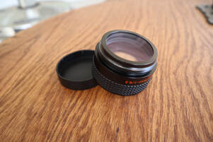
 Celestron's 6.3X focal reducer/field flattener is a very popular accessory for non-Edge SCTs because it reduces the focal ratio of the SCT from its native f/10 to f/6.3. This increases the field of view (FOV) and increases the optical speed of the SCT as well. Both effects are helpful for astrophotography and Electronically Assisted Astronomy as they make shorter exposures possible and allow larger Deep Sky Objects (DSOs) to fit in the camera's sensor. And because it is also a field flattener it will improve the sharpness of the image at the edge of the FOV. The same benefits of a wider field and more intense image apply to visual observers as well Reducing the focal ratio with this reducer speeds up the optics by a factor of (10/6.3)^2 = 2.5. It concomitantly increases the FOV by the same amount. For instance, an 8" SCT with the ZWO ASI533MC camera has a FOV of 19.4 x 19.4 arcminutes at f/10 which increases to 30.8 x 30.8 arcminutes at f/6.3. That is 376 arcminutes-squared vs 949 arcminutes-squared with the later 2.5X the former. For the 8" SCT the focal length reduces from 2000mm to 1260mm with the reducer. Determining the Correct Back Spacing Target For any focal reducer to work as designed It is important to place the sensor of the camera at the correct back spacing, or distance, from the focal reducer. This will ensure that the focal reduction will match the design target, in this case 6.3X. It also ensures that the field flattener works optimally to provide sharp, round stars to the edge of the FOV. If the camera's sensor is placed closer to the focal ratio will be larger, say 6.5X or 7X, and the focal reduction will be less. If it is placed further from the reducer the focal ratio will be smaller, say 6X or 5X, and the reduction will be more. In addition, the field flattener will not perform optimally so stars near the edge of the FOV may be distorted. For astrophotography we want to get the best possible images so we want to be as close to the ideal back spacing as possible. For Electronically Assisted Astronomy (EAA) we may be less fussy about the edge of the FOV and more interested in speeding up the optical system and/or fitting more of the larger DSOs in the FOV. In that case a slightly larger back spacing is sometimes used. Regardless, it is important to know how to get the correct back spacing to begin with. 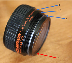 Different locations often identified as the back spacing measurement starting point. 1) Center of the internal lens'; 2) Inner flange; 3) Outer edge of the threads; 4) Back flange. Different locations often identified as the back spacing measurement starting point. 1) Center of the internal lens'; 2) Inner flange; 3) Outer edge of the threads; 4) Back flange. So, how do we achieve the correct back spacing when using the Celestron 6.3X focal reducer? We need to know the correct back spacing and how it is measured. If you search the internet you will find answers ranging from approximately 100mm to 110mm with the most common answer being 105mm. Surprisingly Celestron has not published a spec for the back spacing for this reducer. If you also look to find out where on the focal reducer the back spacing measurement is made, this is where you will find the most disagreement. Some suggest the measurement should be made from the center of the lens' inside the focal reducer (1 in the image above), others from the flat surface on the inside of the threads (2), or the back edge of the threads (3) as shown in the photo. The correct answer to both of these questions is 105mm from the extreme back surface of the focal reducer as shown in the photo identified as location 4 in red. So how do we know that these are correct? 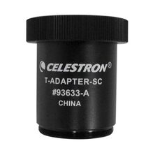 Celestron SCT T-Adapter (50mm) Celestron SCT T-Adapter (50mm) First, we know that the industry standard back spacing for focal reducers used on refractors is 55mm (there are some exceptions). Second, because the optics of an SCT is very different from a refractor it is not possible to make a focal reducer for an SCT with a back spacing of 55mm. So, Celestron did the next best thing. They made an adapter which attaches to the back of the focal reducer and is exactly 50mm long. This leaves the industry standard 55mm left to obtain the correct back spacing of 105mm. Also note that the 50mm length of this adapter is measured from the the flat surface of the flange which mates with the surface "4" in the image above to the flat surface on the other end of the adapter not including the threads where the next spacer will bottom out when screwed all the way on. Similarly, Celestron makes a 7X focal reducer for their Edge SCTs and in this case they do specify the back spacing as 146.05mm. And likewise, they make a T-Adapter to attach directly to this focal reducer which is 91mm long leaving 55.05mm of additional spacing to meet the back spacing spec. So, I think it is clear that the design back spacing for the 6.3X reducer is 105mm and not 100mm, 110mm or something else, and that it is measured from surface 4 on the focal reducer. Imaging Train Options for the 105mm Back Spacing Now that we have established that we need 105mm of spacing for the Celestron 6.3X reducer we need to figure out what options are readily available. But first, we need to take into account the back spacing of the camera sensor itself. This can be found from the manufacturer and we will use ZWO's ASI cameras as an example. Below is ZWO's mechanical drawing for their ASI2600MC camera. This shows the position of the CMOS image sensor relative to the front surface of the camera to be 17.5mm. Likewise the ASI585MC has a back spacing of 17.5mm for the sensor even though it uses a different coupler on the front face. If you look at most cameras these days from ZWO and other manufacturers you will find that 17.5mm is the most common back spacing for the sensor. However, be careful to check as the ASI224MC shown below only has a 12.5mm back spacing. Like plumbing or garden irrigation systems there are many different spacers and adapters available such that one can find many combinations of such to make up the additional back spacing needed. After searching through multiple astronomy supplier's sites I have come up with what I believe to the be the least complicated solutions using the simplest set of adapters available to achieve the 105mm back spacing. I list the parts needed below along with links to either Agena Astro or HighPoint Scientific, two of my goto astronomy suppliers. Links are affiliate links which will earn a small commission at no cost to you. Please use these if you can to support my web site. From Agena Astro Celestron 6.3X focal reducer Celestron 50mm SCT-T Adapter Blue Fireball 37.5mm Extension ZWO 11mm Female to Female Adapter If you want to fine tune the spacing you can use Baader T2 Delrin spacers to adjust the spacing in small increments from 0.6 to 1.4mm. If you want to make larger spacing changes you can search for the desired M42/T2 spacer from Blue Fireball, or substitute the Baader Varilock 46 T2 Variable Extension in place the 37.5mm Extension listed above for greater versatility. Here is an almost identical solution from HighPoint Scientific. Since they do not list a 37.5mm spacer it uses a 30mm and 7.5mm spacer which are sold together as a kit from Celestron. From HighPoint Scientific Celestron 6.3X focal reducer Celestron 50mm SCT-T Adapter Celestron M42 Spacer Kit (30mm + 7.5mm) ZWO M42 Female to Female 11mm Adapter Alternatively to the Celestron M42 spacer kit one could substitute the Baader Varilock 46 T2 Variable Extension which, while almost twice as expensive, allows for variability in the spacing. Also the Baader T2 Delrin Spacer Ring Set is an option for fine tuning the spacing on the order of a mm or less. 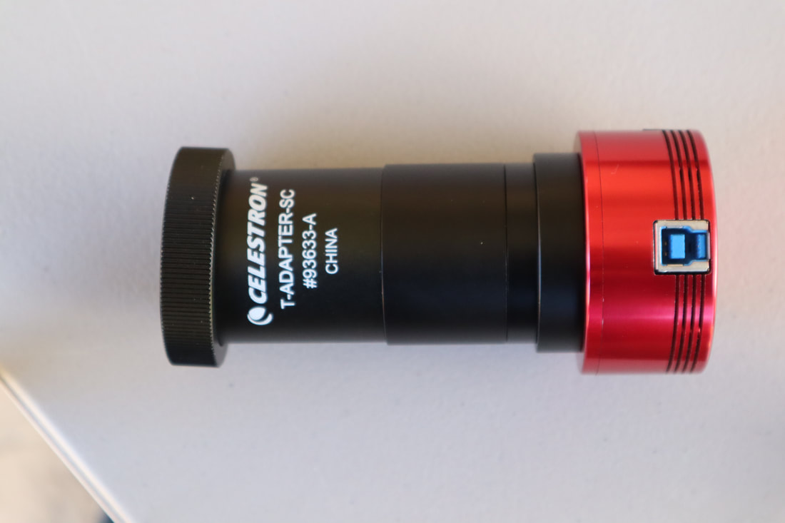 105mm back spacing with ZWO ASI1600MC camera and the adapters/filter listed above from HighPoint Scientific Back Spacing Solutions With a Filter Drawer Now if we want to use filters with our camera we can put a filter drawer in line so that it is easy to change filters in real time. In this case we will need some different spacers and adapters. Also, we need to take into account the fact that the glass of the filter has a different index of refraction compared to air. Filter glass is typically 2-3mm thick so we need to add ~1/3 of that thickness to our optical path for an additional ~1mm. Below is the same setup as above showing the parts needed along with links to either Agena Astro or HighPoint Scientific. Agena Astro Celestron 6.3X focal reducer Celestron SCT-T Adapter Blue Fireball 10mm Extension Blue Fireball 7.5mm Spacer Ring ZWO M42 11mm Female to Female Adapter ZWO Filter Drawer M42 Male to M48 Female ZWO M48 Male to M42 Female Adapter HighPoint Scientific Celestron 6.3X focal reducer Celestron SCT-T Adapter Apertura10mm Extension Baader 7.5mm T-2 Extension ZWO M42 11mm Female to Female Adapter ZWO Filter Drawer M42 Male to M48 Female ZWO M48 Male to M42 Female Adapter 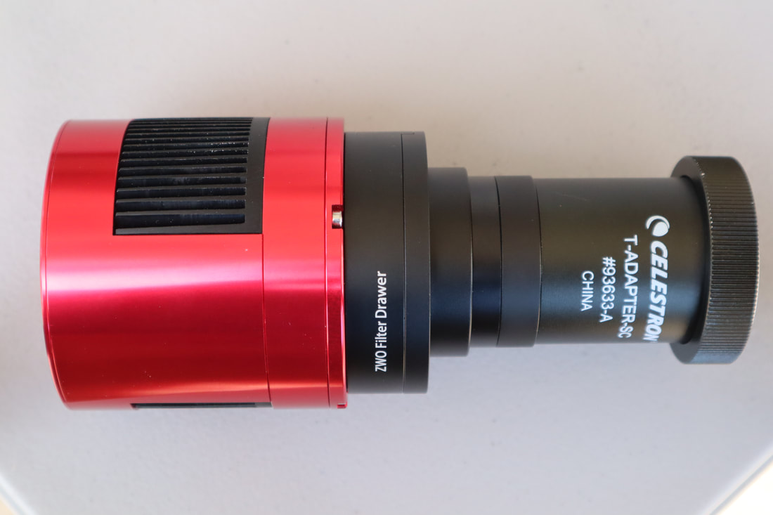 106nm Back spacing with an ASI2600MC camera and ZWP Filter drawer using the adapters/spacers listed in the list from Agena Astro Back Spacing Solutions for SE/Evo/CPC Mounts at 90deg Altitude The solutions above work with cooled and uncooled cameras on any Equatorial mount. In the case of a single arm Alt-Az mount like the Celestron SE or Evolution mounts, or a dual arm mount like the CPC mount, the solutions above will only work as long as the OTA is not pointed higher than ~75 degrees in altitude. Higher altitudes will cause the camera to crash into the base of the mount. A simple solution to reach an altitude of 90degrees without hitting the mount is to add a rail extension along with the imaging trains shown above so that the OTA can be pushed forward to provide enough additional clearance. An inexpensive rail extension is available from SVBony which will work on the 6" SCT. The longer Celestron Universal Mounting Plate is probably a better option for the 8" and 9.25" SCTs and is available from both Agena Astro and HighPoint Scientific. If using a cooled camera there will not be enough room to push the OTA forward and a different approach is needed. This approach uses a diagonal to place the camera at a right angle to the optical axis to gain additional clearance. The details of this configuration can be found in the equipment recommendations section of this web site here. If you would like to see all of these configurations in action, please take a look at the video I put together on this subject where I demonstrate each solution in detail. The video is on my YouTube channel here where you can also find other helpful videos for the amateur astronomer. All links are affiliate links which can earn a commission without any additional cost to you. Please consider using them to help support this channel.
0 Comments
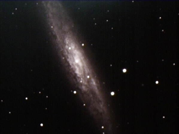 22 sec image of NGC253 Hyperstar on a 14" SCT 22 sec image of NGC253 Hyperstar on a 14" SCT If you own a Celestron SCT and do not already have a hyperstar adapter you should. What is hyperstar? It is a multi-element optical adapter which converts the focal ratio of an SCT from its native f/10 to f/2. Since the optical speed of a telescope is proportional to the square of its f-ratio, adding a hyperstar will increase the speed of an SCT by a factor of 25: speed ~ (10/2)^2 = 5^2 = 25. My first experience with hyperstar was back in 2015 when I first tried it on my 14" SCT to capture a breathtaking view of NGC253 the Sculptor Galaxy in just 22seconds. I was just blown away by what the hyperstar was able to capture in such a short time. Of course, smaller aperture telescopes will not produce such an image in the same time, but they will still have 25X faster optics resulting in amazing images in short times of their own right. Hyperstar is available for the 6", 8", 11" and 14" Celestron Edge and non-Edge SCTs and the 9.25" Edge version. It has been available for these models for some time. Just check the front of the Secondary mirror for the phrase "Fastar", where Fastar is the original Celestron name for this, to see if your older model is compatible. For those that do not say "Fastar" a conversion kit is available for all 6" through 14" models except the 9.25" model. 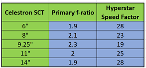 How does hyperstar work? An SCT consists of three optical elements, a corrector plate at the front, the primary mirror in the back and the secondary mirror in the center of the corrector. SCT primaries are spherical mirrors configured to a focal ratio of f/2. Actually the focal ratio of a Celestron SCT primary varies between f/1.9 and f/2.3 depending upon the model as shown in the accompanying table. For the sake of simplicity, lets stick with f/2 as our example. The secondary mirror is figured to a focal ratio of f/5 so the combined effect is a focal ratio of f/10, f/2 x f/5 = f/10. 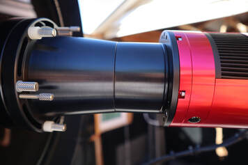 The camera adapter is seen between the hyperstar and the camera. The camera adapter is seen between the hyperstar and the camera. Hyperstar is installed by removing the secondary mirror and replacing it with the hyperstar compound lens. With no secondary the focal ratio is that of the primary mirror, or f/2. Obviously the hyperstar element can only be used with a camera for imaging, either for traditional astrophotography or electronically assisted astronomy, and not for visual observations. A camera is attached to the hyperstar via an adapter which is specific to the camera and hyperstar size. The light enters the SCT through the front corrector plate and reflects off the primary mirror just as it always does. But now, instead of reflecting off the secondary mirror back through the center of the primary and out the back of the SCT, it travels through the optical elements of the hyperstar and into the camera. The hyperstar is a multi-element lens/corrector which not only focuses the light onto the sensor in the camera, but also corrects for the spherical aberrations and field curvature which would be present without the corrective capability of the hyperstar. Images taken with the hyperstar should be sharp and flat across the field of view. Hyperstar can be used for both traditional astrophotography and electronically assisted astronomy. In both cases, the faster focal ratio enables more light to be collected in a given time compared to the SCT's native focal ratio of f/10. The results can be stunning as in the traditional astro photo of M31 shown below taken on a C11 with hyperstar for a total exposure time of 213 minutes using Pixinsight to combine and process hundreds of sub-frames. Similarly, amazing results can be obtained during live stacking and viewing during an EAA session as seen in the image of the Rosette Nebula taken with TSX's Live Stack feature stacking and stretching 120 x 5 sec sub-frames for a total of 10 minutes also using a C11 with hyperstar. 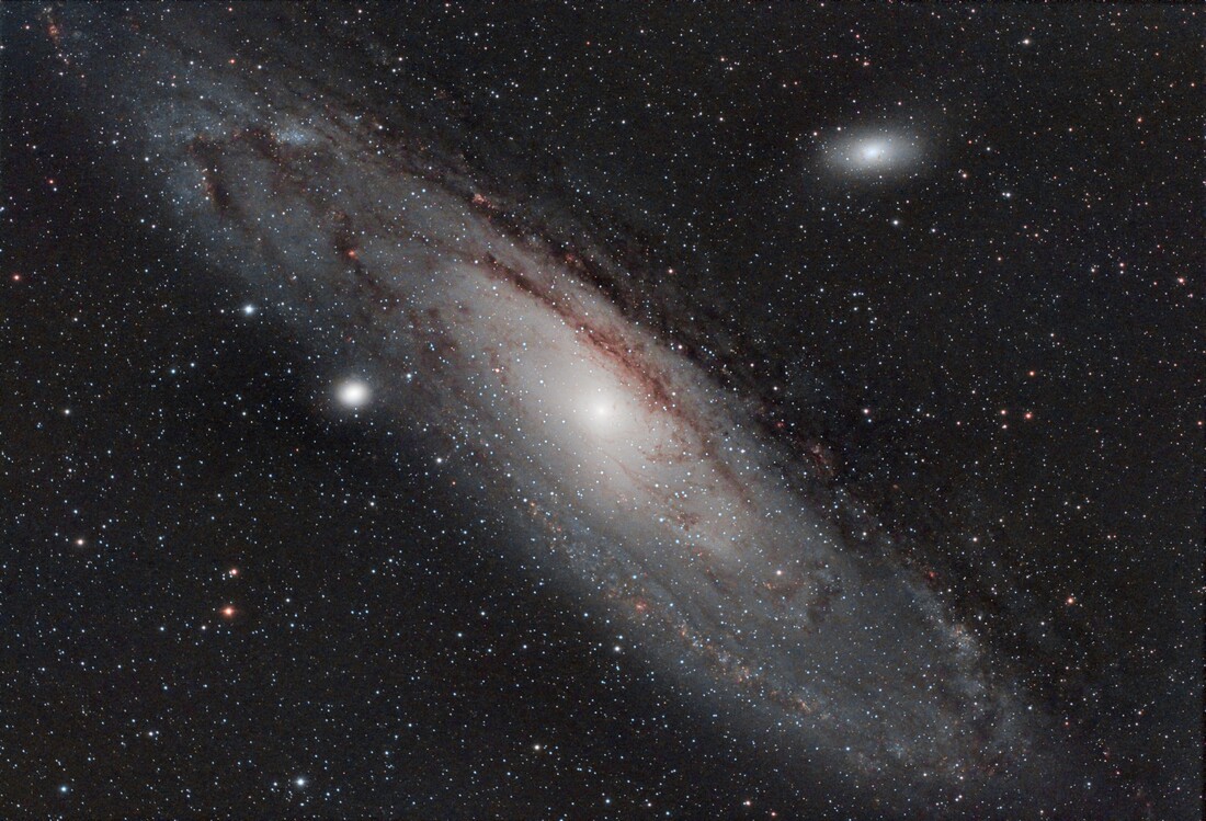 Traditional astrophoto of M31 taken with Hyperstar on a C11 with an ASI294MC Pro Camera 213min stack 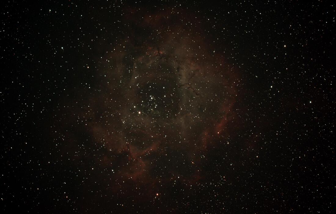 Live stack image of the Rosette Nebula taken with Hyperstar on a C11 with an ASI2600MC Pro camera with a total stacking time of 10min 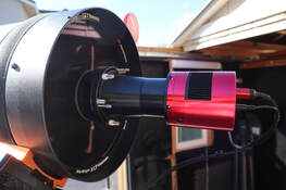 A C11 with hyperstar and an ASI2600MC A C11 with hyperstar and an ASI2600MC Installing Hyperstar Removing the secondary mirror from your SCT may sound scary but it really is a simple matter. I like to set the OTA at a slightly elevated angle so it is easy to reach the secondary and gravity will still help to keep it in place when its retaining ring is removed. The secondary slides out and can be placed into the protective holder which comes with the hyperstar. The hyperstar is threaded onto the secondary holder. But be careful not to over tighten the hyperstar. Finger tight is sufficient. I once got the hyperstar so tight that I had to remove the corrector plate to get it back off. You should not have this problem if you do not over tighten the hyperstar like I once did. After installing the hyperstar several times you will even feel comfortable doing this in the dark. The procedure should take only 5min or less. While hyperstar can weight as much as 3lbs for the 14" SCT it is not going to damage your corrector plate when handled carefully. An SCT corrector plate is much stronger than one may realize. Still, I would never transport an SCT with a hyperstar installed as the possibility of banging into the hyperstar is always present. Also, when covering the telescope using a hyperstar with an all weather cover just be careful that the cover does not snag on the hyperstar which protrudes from the OTA. I leave my hyperstar on for multiple days while in the field using a dew shield and cover over the hyperstar and correct which keeps dirt and dust off the corrector. At home I leave my hyperstar mounted on my SCT in the backyard observatory as long as I plan to work at f/2. There is really no need to remove and re-install hyperstar every day. 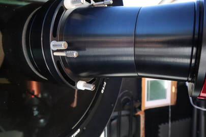 Push/Pull collimation pins at left and a rotation thumbscrew at bottom Push/Pull collimation pins at left and a rotation thumbscrew at bottom Hyperstar Collimation Just like the secondary mirror on an SCT, hyperstar will need to be collimated from time to time. Fortunately, hyperstar seems to hold collimation just as well as a secondary mirror so you should not expect to need to collimate any more frequently than you do without it. Also, you most likely will not need to re-collimate your scope when you put the secondary back since it is indexed to the optical axis with a pin which fits into a notch in the flange which holds the secondary. Hyperstar has 3 sets of push/pull pins located at 120 deg increments around the outside for the purpose of collimation. There are two strategies for initial collimation. The simplest takes advantage of the high precession machining of the two hyperstar mechanical bodies. Just adjust the push/pull pins so that both flanges of the hyperstar bodies are in contact all the way around and then tighten the pins. So long as these two flanges are parallel to one another and the corrector plate is aligned with the primary mirror you should have good collimation. Several folks have reported that this has worked for them so it is worth trying first. If you are not satisfied with the collimation with that approach you can use the second method. With this approach you will need 3 shims 30 to 40 mil thick. Metal stock of this type can be found at your local Ace hardware or online. I use Cu stock which I cut into 3 pieces long enough to fit between the two hyperstar flanges. With the shims spaced 120 degrees apart between the two hyperstar flanges, tighten the push/pull pins just enough so that you can barely pull the shims out. Make sure that you tighten pins are engaged so that the flanges do not come loose. Then, under the stars perform a collimation as you normally would using the push/pull pins in the same way as you would the 3 screws on the back of the secondary mirror. You will find that it is a lot easier to adjust the push/pull pins with your fingers. Just make sure they are all tight when you are satisfied with collimation. A very large variety of cameras are compatible with hyperstar including those from ZWO, QHY, ATIK, SBIG, etc. When ordering the hyperstar element you will need to specify the camera that you will use with it since a camera adapter is required to attach the camera to the hyperstar lens at the optimum distance from the camera sensor.  Hyperstar filter drawer and slider Hyperstar filter drawer and slider Using Hyperstar The hyperstar adapter has 3 thumbscrews which are designed to allow 360 degree rotation of the hyperstar so that you can adjust the orientation of your camera. Just loosen all three thumbscrews 1/4 turn, rotate the the outer body of the hyperstar to the desired orientation of the camera. Then tighten the thumbscrews to lock the camera orientation. Since these thumbscrews hold the two halves of the hyperstar together, you should never completely remove them. USB and power (if needed) cables are attached to the camera as usual. If you are using a dew shield you can either bring the cables out the front of the shield or, out the back of the shield if it has a notch in it. In either case tie off the cables so they do not drag. In some cases, the cables may produce diffraction spikes on bright stars just like the spider vanes on a Newtonian secondary. This can be minimized by avoiding running the cables in a straight line across the front of the OTA. The hyperstar camera adapter is threaded inside so that a filter can be attached. This works well if you intend to use only a single filter, such as a light pollution filter, a UV-IR filter or a multi-band filter during you imaging session. Just unscrew the front piece on the adapter, screw in the filter and screw the adapter/filter combination back on. Then attach the camera. If you want to change filters during a session you will need a filter drawer for the hyperstar. The filter drawer screws onto a separate hyperstar adapter such that the combination provides the correct backspacing for your camera. Everything else in an imaging or EAA session will be the same as if you did not have the hyperstar except it will require much less time to be able to see DSOs compared to operating at f/10. Wide Field Since the hyperstar reduces the focal ratio to f/2 but does not reduce the aperture of the telescope, the field of view will be much wider. In fact, the field of view will also be 25X larger compared to f/10, 5X in each axis of the camera sensor. This is precisely how the hyperstar speeds up imaging. To understand this let's take a look at the difference in image scales at f/10 and f/2. Image scale depends upon the size of the pixels in the camera and the focal length of the telescope. It is defined by the following equation: Image Scale (arc-sec/pixel) = 205 x pixel size (microns) / focal length (mm) So, for the same camera, the image scale varies inversely with the focal length. In other words, the image scale increases as the focal length gets smaller. Adding the hyperstar reduces the focal length proportional to the reduction in focal ratio. For the C11 discussed above the focal length is reduced from its native 2794mm to 559mm with hyperstar. The image scale is then reduced by the same factor of 5 across the x and y axis of the camera chip. This means that each pixel is collecting light from an area of the sky 25X larger with the hyperstar than without the hyperstar which is why the exposure time is reduced. Keep in mind that with the wider field of view the resolution is now reduced by the same amount. But since seeing conditions usually dominate image resolution stars and most CMOS cameras used for astronomy have sensors with pixels smaller than 4microns on a side the image quality will still be excellent, even if you zoom in on the image. Summary
Hyperstar is certainly expensive costing just under $1000 for an 8" SCT and more for larger apertures. However it should be viewed as turning your f/10 SCT into a completely new telescope with a focal ratio at least 4X faster than the fastest refractors available while maintaining an aperture many times larger than a refractor. Think of it as investing in an entirely new scope but without having to purchase a new set of accessories (finder, dew heater, focuser, etc.). As the few images shared here show, hyperstar can produce incredible images in real time and is well suited to capturing more of the larger DSOs. If you want to see more about the amazing hyperstar check out my hyperstar YouTube video Links are affiliate links which can earn a commission without any cost to you. Please consider using them to help support this web site. Hyperstar is available from HighPoint Scientific bit.ly/3RO8vgv 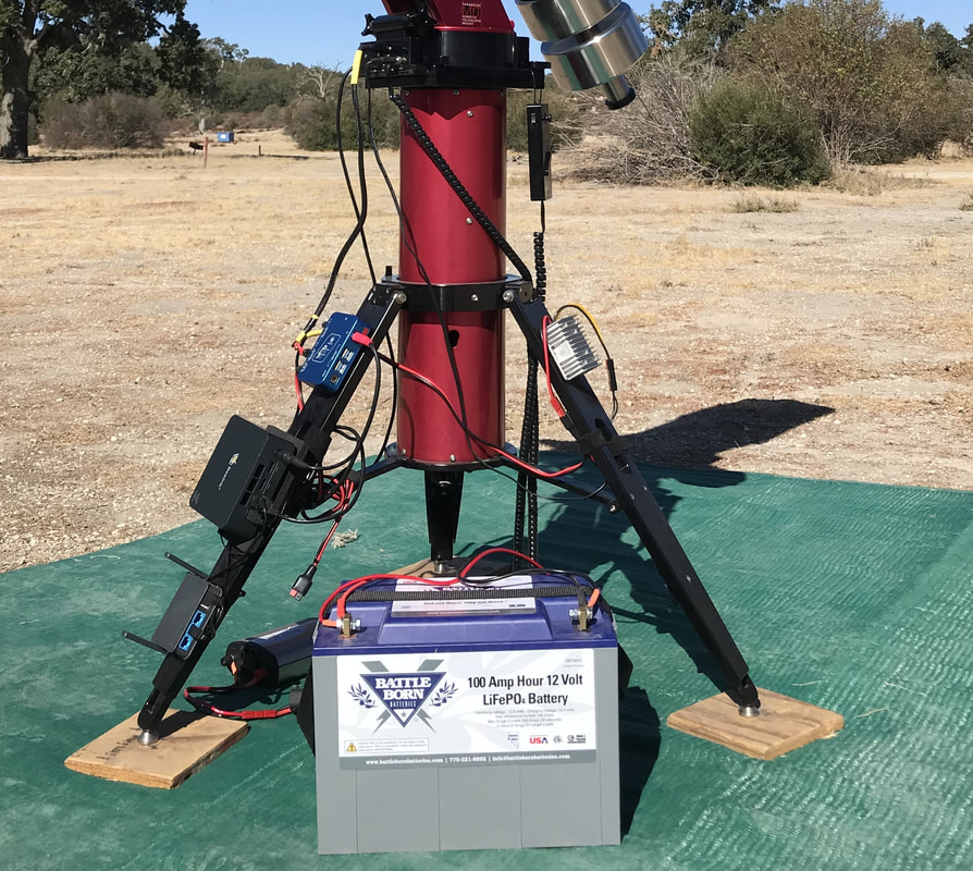 Mini-pcs are becoming increasingly popular for both Electronically Assisted Astronomy (EAA) and astrophotography. This is because a mini-pc allows one to connect remotely to the telescope, mount, camera, and other equipment with a laptop, tablet or phone without being tethered by a USB cable. Remote may mean inside one's house while the telescope is out in the back yard or inside a small tent or EzUp where you can stay comfortably warm and away from annoying bugs when observing away from home. It may even mean sitting in your own house with your telescope set up at a distant remote observatory. In my case, it means being inside my house when observing at home with my equipment setup in the backyard observatory or inside my RV when at a star party or other remote site. Being untethered allows me to move freely from inside (house or RV) to the side of the telescope whenever I need to be close but then being able to return to the inside for most of the night. Utilizing a mini-pc at the telescope will also reduce the power required to keep everything running through the night. A mini-pc uses much less power than a typical laptop. If you connect remotely to the mini-pc with a laptop you can still save power since you do not have to have the laptop on all the time since it is only being used as a monitor to check in on the mini-pc from time to time. In fact, you can simply turn off the laptop once the mini-pc is up and running and leave it off until you are ready to shut down the session. A tablet or phone can be used instead of the laptop to remote into the mini-pc which gives more options in terms of saving power since these use much less power than a laptop. What is a Mini-PC? A mini-pc is a headless computer which comes in a small form factor typically 5" - 6" on a side by about 2" - 3" thick or even smaller. Headless means that it comes without a monitor, keyboard or mouse. This cuts down on the size, cost and power consumption, all important for astronomy applications. Since a mini-pc is a computer it will have a CPU, RAM, non-volatile memory, a GPU, USB and HDMI ports, a LAN port, WiFi, and Bluetooth capability. It will also come with an installed operating system such as Windows 10 or 11. The mini-pc can do anything a laptop can while running the applications needed for complete control of mounts, cameras, focusers, dew heaters, etc. This includes running image capture software, guiding software, planetary software, plate solvers, planning software and imaging session automation and control software like NINA or SGP. For instance, on my mini-pc I have The Sky X for mount/camera/focuser control and image capture, Sharpcap for EAA, Ph.D2 for guiding, All Sky Plate Solver and ASTAP for plate solving, Cartes du Ciel as my planetary software, and Sky Tools 3 Pro for planning. I recently added NINA which will take responsibility for overall control and sequencing of my astro-imaging sessions which still uses TSX, Ph.D and ASTAP. In general, a mini-pc is not expected to do the heavy lifting of post processing the photos captured during an astrophotography session, although it is expected to handle the live image stacking, dark frame subtraction and stretching typical in an EAA session. Usually, the burden of post processing astro images is tasked to a separate, more powerful and more expensive laptop or desktop computer. But, there is no reason it cannot be done on the mini-pc if configured to do so which requires a keyboard, mouse and monitor. Even when post processing is left to a separate computer, it is imperative to have a keyboard, mouse and monitor to attach to the mini-pc for initial setup and for analysis in case something goes wrong. In two years I have only had to pull out these once in the field and it turned out that the problem was operator error, not something wrong with the mini-pc or my WiFi router. Still, having these as backup is essential in the rare case that something goes wrong.  My Beelink U57 with 5th Gen Core i5, 8GB RAM and 256GB SSD My Beelink U57 with 5th Gen Core i5, 8GB RAM and 256GB SSD Choosing a Mini-PC When it comes to mini-pcs there are a seemingly endless number of options available which constantly change as new hardware components become available. New mini-PCs can be found for under $200 on models with Celeron and Core i3 processers to over $1000 for models with high end processers, GPUs and lots of memory. Keep in mind that even with the same models, prices fluctuate frequently both up and down. The correct choice depends upon one's particular application, future plans and pocketbook. Typically, the trade off in performance and price leads to mini-pcs used for astronomy costing somewhere between $200 to $500. Beelink is probably one of the most popular mini-pc manufacturers in this price range. Recently, inexpensive models from Mele Quieter have gotten a lot of notice on the Cloudy Nights forum as well. Intel NUCs (Next Unit of Computing), designed and built by Intel, are also quite popular and include some of the high end mini-pcs as these NUCs come in many configurations including kits which can be customized to the users requirements. 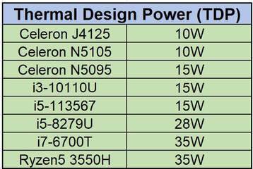 When choosing a mini-pc the first feature to consider is the CPU. At this point in time mini-pcs used for astronomy usually include a Celeron or Core i3 processer for the less expensive models or an i5 processer for the slightly more expensive models. Many people report success in astrophotography and even EAA with mini-pcs using Celeron processors. However, for high data rate applications as is the case with larger format cameras (20Mpixels or larger) or live stacking of very short exposures (less than 5 sec subs) with dark frame subtraction and flat frame calibration for EAA, the Celeron class of processor may not be up to the more challenging tasks. In these situations an i5 processor would be a safer choice while the added cost of an i7 processer might be better applied to more RAM or a larger and faster SSD. For planetary imaging requiring extremely high image capture rates one should consider at least an i5 and possibly an i7 processor with fast SSD storage. Celeron processors found in these mini-pcs include the Gemini Lake J4125 and the Jasper Lake N5095. For Core i5 processers the Tiger Lake 113567 and Coffee Lake 8279U are typical. In addition to processing speed and cost another attribute of CPUs to be considered is the Thermal Design Power (TDP) which is indicative of the maximum power that the CPU can generate. The higher the TDP the more power one needs in the field to keep the mini-pc running all night long. One of the desirable features of the mini-pc is its lower total power consumption compared to a laptop. The accompanying table shows the tradeoff in CPU capability and TDP. After the CPU the amount and type of RAM and mass storage is probably the next most important consideration. 8GB of RAM is sufficient for most situations and is fairly common in pre-configured mini-pcs, while 16GB can help when many applications are open at the same time. As far as mass storage one should consider 128GB to be the minimum choice in which case you may have to constantly download image files to another storage device after an imaging session. I opted for 256GB which allows much more margin, but even then I sometimes wish that I had paid the extra for 512GB. The choice will depend on your imaging/EAA habit and how often you are willing to transfer images from your mini-pc to your processing pc. Mass storage on the mini-pcs often used for astronomy typically have one of three types of mass storage including M.2 SATA SSDs, M.2 NVE SSDs or eMMC. The first two can be replaced while eMMC is soldered onto the motherboard and cannot be replaced. NVE SSDs use the PCIe interface which is much faster than the SATA interface used by SATA or eMMC devices. All will work but the M.2 NVE SSD is the better choice for high data rate applications. Probably the next most important consideration in choosing a mini-pc is the number and type of USB ports because of the need to connect our many astro devices to the mini-pc. Most mini-pcs in the price range being discussed usually provide at least 4 USB ports in some combination of USB2.0 and USB3.0. Some also provide a USB Type C port with even faster data transfer rates. Don't forget to reserve one USB port for a WiFi dongle when using a wireless keypad and mouse. On other hand, if like me, you have a USB hub like the Pegasus Power Box which you use to connect your astro devices, you will only need to connect the hub to the mini-pc, preferably over a USB 3.2 port for fastest transfer rates. Another choice is whether or not to choose a mini-pc with a fan or not. Fans consume additional power. And they can, in principle, cause vibrations although I have never witnessed any such problem with my mini-pc attached to the leg of my tripod. On the other hand, fans will keep the CPU cool so that it can operate at its highest speed whereas air cooled mini-pcs can get hot causing the CPU to throttle back. Beelink tends to incorporate fans into their models while MeLE Quieter does not. Many folks agonize unnecessarily over the fact that some mini-pcs require 19V power input instead of 12V. This is easily rectified with an inexpensive DC-DC boost converter which takes a 12V input and provides a steady state 19V output. The boost converters are ~95% efficient while the AC transformer typically supplied with any mini-pc is likely ~80% efficient. I find the easiest way to incorporate these into my setup is to attach Anderson Power Poles to the leads and use Anderson Power Pole to 5.5 x 2.1mm adapter cables to connect to my equipment. All mini-pcs include an ethernet port for wired connection, WiFi and BT capability, along with one or more HDMI ports. You will need one HDMI port to connect a monitor initially to set up the mini-pc and any time something goes wrong with your connection to the mini-pc and you need to trouble shoot the situation. Mini-pcs come with Window 10 or Windows 11 software already installed. Look for the Pro version which is required for some remote connection software like Team Viewer and Remote Desktop. 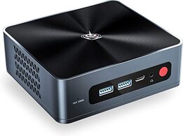 Beelink SEI8 Beelink SEI8 Mini-PC Models to Consider Below are a number of different mini-pc models currently available. Prices will vary and over time models will change, but this can be a good starting point. Beelink has a large following in the astronomy community judging from posts on CN and is the brand I have used and been happy with for the past 2 years. You can search through all their models on the Beelink Amazon store. A few examples are worth considering. The Beelink U59 Pro comes with a Celeron N5105 processor, 8GB of RAM, a 500GB M.2 SATA SSD, 4 x USB 3.0 and 1 x USB C ports, 2 LAN ports, 2 x HDMI ports, WiFi, BT, and Windows 11 Pro. It has a cooling fan and operates on 12V and is currently on sale for $219. You can add 8GB more RAM for another $25. The Beelink SEi8 has an i5-8279U processor, 16GB of RAM, a 500GB M.2 NVME SSD, 4 x USB 3.0 and 1 x USB C ports, 1 LAN port, 2 x HDMI ports, WiFi, BT and Windows 11 Pro. It also has a cooling fan and operates on 19V and also has an auto startup feature so that you can set it to automatically turn on at a set time each day. This model is currently on sale for $397. Compared to the model above you get a faster processor, twice the RAM and a faster SSD. 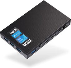 MeLE Quieter 2Q MeLE Quieter 2Q If you are looking for a fanless mini-pcs, the models from MeLE Quieter are becoming popular among amateur astronomers lately. Here are two worth considering. The MeLE Quieter 2Q uses the Celeron J4125 processor, 8GB of RAM, 128GB of eMMC storage, a Micro SD card slot of storage expansion, 4 x USB 3.0 ports, 1 LAN port, 2 x HDMI ports, WiFi, BT and Windows 11 Pro. It does not have a cooling fan and can also be configured for auto startup. This model is currently on sale now for $210. Like most mini-pcs there are upgraded versions of this model with up to 512GB of eMMC storage for an additional $90. The MeLE PCG35 has a Celeron N5105 CPU, 8GB of RAM, a 256GB NVMe M.2 SSD, a Micro SD card slot of storage expansion, 2 x USB 2.0 and 2 x USB 3.0 ports, 1 LAN port, 2 x HDMI ports, WiFi, BT and Windows 11 Pro. It does not have a cooling fan and can also be configured for auto startup. This model is currently available for $310. Both of these MeLE models require 12V input power. Intel NUCs can be found at the Intel Store for as little as $200 to well over $1000. An example is the Intel NUC 10i3FNHN which currently lists for $499 and includes an i3-10110U processor, 8GB of RAM, an 512GB of PCIe SSD, 3 x USB 3.2 ports, 1 Thunderbolt (Type C) port, 1 HDMI port, 1 LAN port, BT, WiFi, an SD card slot and Windows 10Pro. It requires 19V for power.  GL.iNet Slate Portable Router GL.iNet Slate Portable Router Mini-PC Operation Being small and light, a mini-pc can be mounted on top of the telescope which minimizes the length of cable runs between cameras, focusers, dew heaters, filter wheels, the mount and the pc. Often the mini-pc can be found mounted to the leg of the tripod or at the base of the mount. If the mini-pc has a cooling fan, this may be the best place to mount it to minimize the chance of vibrations in the optical system. This is my typical configuration since I have a Software Bisque Mount with through the mount cabling. In addition to the mini-pc some method to connect between a laptop/tablet/phone and the mini-pc is required. This involves a remote desktop application like Team Viewer, VNC Connect, Remote Desktop or one of the many others which are free and easy to use. These generally require that the mini-pc has the Pro version of Windows to work. The second requirement for remote connection is the ability to make a WiFi connection. At home this could simply be your home internet network assuming that you have a LAN line to connect to the mini-pc in the back yard. I use a Cat5 cable I strung out to my backyard observatory 10 years ago to connect from my laptop anywhere inside the house to my mini-pc outside on my home network. In the field or at home if you don't have a wired connection in the back yard, you will need to create your own WiFi network. This is simple to do with an inexpensive portable router. I have reviewed 2 such inexpensive routers from GL.iNet in an earlier blog which you can find here. A video version of my review can also be found here. I have been using the GL.iNet 750S Ext (Slate) for 2 years and could not be happier. I can stay connected from inside my RV to my telescope up to 100 feet away. At home I can use the Slate as a repeater and connect to my home internet without the need for a LAN cable connection. GL.iNet has another model capable of higher data rates called the Beryl for just a few dollars more which is worth considering. If you need help setting one of these up, I created a video showing how to do this step by step. Summary Having used my mini-pc for two years both at home and at many star parties I have been extremely happy that I finally made the move to untether myself. With one exception (operator error) I have not lost any time due to problems connecting or using the mini-pc. And, I have not noticed any problems when using it for astrophotography or EAA. Hopefully I have given you a helpful overview of the considerations required to set up your own remote connection so that you can make the right choice for your situation. The one possible downside of using a mini-pc is that it tends to keep me inside, even at star parties, instead of out under the night sky. I have had to remind myself that one of the great things about being at a star party is to be able to look up and appreciate the wonder of the Milky Way with my naked eyes. So, I make it a point to spend some time outside both viewing the night sky and talking with my fellow amateur astronomers instead of spending the entire night away from the action inside the RV. You can find a complementary video tutorial on this subject on my YouTube channel which you can find here www.youtube.com/watch?v=TRk2wsrOnNM Beelink Mini PCs amzn.to/48Vp3Lm
MeLe Quieter Mini PCs amzn.to/47KLXUK Intel NUCs amzn.to/47KM1ns GLi.Net Portable Routers amzn.to/4b1oamt Links are Amazon Affiliate links from which I can earn commissions at no cost to you. If you would like to support my web site and its content please consider using my links when ordering products. 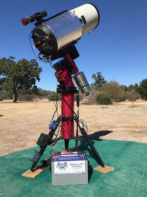 Two years ago I decided that I was no longer willing to have my laptop tethered to my telescope with a long USB cable. When I am in the field I normally site inside my EZUp tent with my laptop to stay warm and to limit the light infringement on my neighbors. While this has worked well for many years, the cable presents a tripping hazard especially at star parties where other folks tend to stop by. And now that I have an RV I want to sit inside and not worry about running a USB cable through an open window or door. So, I looked into what is needed to go wireless and found that it was not at all difficult. First, we need computing power at the mount to run all of the software used to control the mount, camera, focuser, guider, dew heaters, etc. Second, some sort of WiFi either built into the computer or through a small travel router is required to link the computer at the mount to the device inside. Third, software designed to allow a laptop, tablet or phone to be connected to and control the computer at the mount is also needed. Let's look at each of these in detail. Off the Shelf Solutions There are a number of different ready made solutions available from the astronomy industry. On the high end there is TheSky Fusion (available from High Point Scientific) from Software Bisque. At the heart of the Fusion is a 64bit Hex-Core CPU with 4GB of RAM which drives TheSky imaging addition software which is included with the Fusion. A total of 190GB of on board memory is available to store images. It has an integrated WiFi with an external antenna to provide wireless connection to a pc, laptop, tablet or phone. It also comes with an ethernet port in case of the need for a hard wire connection and it has internal GPS. TheSky Fusion integrates USB hub capability with 4 USB3.0 ports and can operate as a power distribution hub with 8 configurable power ports capable of supplying up to 40A using Anderson Power Pole connectors for reliable connections. At 4.2lbs the Fusion is designed to be mounted on top of the telescope to allow for simpler cable management. With a price of $1895 TheSky Fusion is on the high end of off the shelf WiFi solutions but it is certainly packed with useful features combining the functions of a computer, WiFi, USB hub and power distribution all in one. Another high end solution comes from Prima Luce Labs in their line of four different telescope control units ranging in price from $795 to $2195. The least expensive model is the Eagle LE (available from High Point Scientific) while the most expensive model is the Eagle 4 Pro (available from High Point Scientific) The LE has an Intel Celeron Dual Core CPU with 4GB of RAM and 120GB SS memory while the Pro has a Quad Core I5 CPU with 16GB of RAM and 480GB of SS memory. Both provide connectivity via WiFi with an external antenna and through an ethernet port. Both models have ample USB ports and 7 power ports, 3 of which allow voltages to be configured from 0V up to 12V. The Pro model includes a GPS. Any software can be installed onto these units just like a normal pc and, like the Fusion, these units are designed to be installed on top of a telescope. The Eagles use proprietary connectors on the 4 12V non-configurable power ports so one has to add the cost of these cables to the total cost of the unit. Like TheSky Fusion Prima Luce Labs' models combine multiple capabilities into one device. ZWO's ASIAIR Plus (available from High Point Scientific)is a much less expensive WiFi solution but with less computing power and fewer bells and whistles. At the heart of the Plus is a Raspberry PI 4 processor with 32GB of internal storage and a slot for a MicroSD card. It has an external WiFi antenna and an ethernet port. Unlike the models from SB and Prima Luce Labs, the ASIAIR will only work with ZWO cameras, focusers and filter wheels but it will work with a large variety of mounts. Like the SB and PL units it also acts as a USB hub with 4 USB ports and a power distribution hub with 4 12V power ports capable of a total of 5A. The ASIAIR is also designed to be mounted on top of a telescope but has a much smaller footprint than the SB and PL units and weighs less than 0.5lbs. At a price tag of $299 the ASIR Plus is a slimmed down version both in size and capability of the more expensive SB and PL models. The Stellarmate Plus is the least expensive ready made WiFi solution at $229. Like the ASIAIR it uses a Raspberry PI 4 processor, has 2GB of RAM and includes a 32GB MicroSD card for storage. In addition to the WiFi the Stellarmate also has an ethernet port but no external WiFi antenna. It has 4 USB ports but no external power ports. Like the ASIAIR the Stellarmate is compact and light weight. Unlike the ASIAIR, Stellarmate works with a wide variety of astronomy equipment. It includes a copy of EKOS Astrophotography software and is compatible with a variety of other software applications. 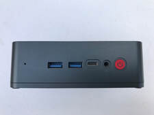 Beelink Mini-Pc 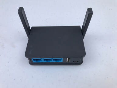 GL.iNet AR750S Portable WiFi Router GL.iNet AR750S Portable WiFi Router Build Your Own Solution While the above ready made wireless solutions will work, each has its cons. The high end models are expensive and better CPUs, and more RAM and memory can be found for less money. The lower cost models only come with a Raspberry PI processor, which works, but is limited in ultimate capability and they have very little RAM and memory. With just a little bit of effort, and not much more cost, if at all, compared to the ASIAIR and Stellarmate options, one can put together a better custom tailored solution on their own. I chose to build my own solution with the features and capabilities that I wanted. A custom WiFi solution requires three components. The first is a CPU at the mount to run all of the software used to control the mount, camera, focuser, guider, dew heaters, etc. This could be an inexpensive laptop, a headless Intel NUC or mini-pc, or a home brew Raspberry PI. I decided that the best solution for me was a headless mini-pc because it offered the best price to feature ratio. I bought a Beelink U57 mini pc with an Intel Core I5 processer, 8GB RAM and a 256GB solid state drive for under $360. And considering that I use a Pegasus Power Box Advanced which cost $330 I have all of the features that TheSky Fusion offers that I need for less than half the price. The mini pc comes with Windows 10 Pro installed so that I can run any of the typical software that I use such as The SkyX for mount/camera/focuser/guider control and image capture. I can also use SharpCap if I want to do electronically assisted astronomy (EAA), PhD for guiding, Nina or Sequence Generator Pro for image sequencing, etc. I am also not constrained to work with any one manufacturer's equipment as a mini pc works with any mount, camera and accessory that is ASCOM compatible. While my model is no longer available, you can find something similar for just $249 or choose from a wide variety of mini-pcs from Beelink with different processors, RAM, memory, USB ports, etc. While my mini-pc uses 12V, most mini-pcs or Intel NUCs require 19V which can easily be supplied using a 12V battery and a 12V to 19V DC-DC voltage converter like this one. The second component is WiFi. I found two inexpensive portable wireless routers from GL.iNet that I bought and tested, the GL-MT300N (Mango) and the GL-AR750S (Slate) models. The 750S provided greater range due to its pair of fold up antennas and also offered 5GHz capability which helps to mitigate potential interference on the 2.4GHz band from nearby equipment. I am able to set up inside my RV up to 100 feet away from the mini-pc and maintain a good connection all night long with the Slate. I can also set up just inside my house and stay connected to the mini-pc inside my backyard observatory when at home. You can read my review of the Slate and its smaller Mango alternative in my Feb '21 Blog or view my video review of these two on YouTube. There is a newer model with fold up antennas, the GL-MT1300 (Beryl), which offers twice the data rate of the Slate. The last component to make this all work is a way to make the remote connection from the laptop (or tablet or phone) to the mini-pc to use the laptop as a terminal to view and control the software on the mini-pc. There are many free remote connection options and I tried two of them, Remote Desktop and Team Viewer. I chose Team Viewer but any of the many options will work fine. The choice seems to come down to personal preference. Also, you will most likely need to have the Pro Version of Windows software installed in order to use the remote connection software, but most of the mini-pcs seem to come with that. 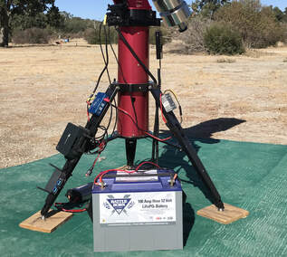 Router - Mini PC - PPBA On Tripod Leg Router - Mini PC - PPBA On Tripod Leg Set Up & Operation
I choose to have my mini-pc attached to the leg of my telescope tripod since my SB MyT mount can supply all the power I need to the cameras and focuser through the mount itself. I also have through the mount wiring for the dew heater. For some people this will work, but others may choose to set up the mini-pc or Intel NUC on the telescope itself. These are small enough and light weight enough as to add little inertia to the telescope. The Slate router gets its power from the mini-pc. Power to everything comes from a LiFePO4 battery or Jackery solar generator which is fed through the Pegasus Power Box Advanced. I just power up the PPBA, turn on the mini-pc and the mount and step away to my laptop. It takes a few minutes for the router to set up its WiFi signal which I connect to with my laptop. Once connected to the router I run Team Viewer to connect to the mini-pc and begin my session with The SkyX and any other software that I need which resides on the mini-pc. Images are captured difrectly to the mini-pc and retrieved later for post processing on my laptop. When my session is over, I simply park the mount, turn off the cameras and close The SkyX and any other software (ShapCap, PhD) that I have running on my mini-pc. Then I turn off the mini-pc remotely. I can leave everything like this or I can go over to the telescope and disconnect the battery or turn off the Jackery. Additional Considerations If you go the route of a headless mini-pc or NUC I suggest that you carry with you a mouse, keypad and small LCD display. This way, if something goes wrong you can connect to the mini-pc and see what is going on. You can use a wired mouse and keypad you may already have lying around or you can purchase a wireless set similar to the one I did. You will also need a small LCD display and there are many to choose from. It is also worth knowing that the wireless routers I discussed above can also work as WiFi repeaters at home which is how I use mine. The router can be set up to connect to the home WiFi and then I can use my laptop from anywhere inside my house to connect to the mini-pc out in the observatory. Of course, how well this works depends upon the strength and coverage of your home WiFi signal, but it is a nice additional advantage of the wireless router if you do not already have either WiFi or cable at your backyard observing location. Summary For those who prefer ready made solutions there are several very good options which we discussed to choose from across a broad range of prices and features. However, if you are inclined to set up your own system you can customize it to your specific needs, including only those elements that you need and avoid paying for features you do not want. And, a custom solution will give you the greatest flexibility in terms of equipment and software compatibility. You can find a companion video I made on this topic here www.youtube.com/watch?v=quoWbvN5VWc&t=1220s Some links are Affiliate links where I can earn with purchases at no cost to the buyer which help to support this web site. If you would like to support my web site and its content please consider using my links when ordering products. 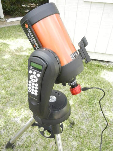 Celestron 6SE with ASI224MC Celestron 6SE with ASI224MC Why SCTs In this installment of my "EAA for Beginners series" we will discuss the use of a Schmidt Cassegrain Telescope (SCT) for EAA on an Alt-Az mount. SCTs seem to be a popular choices for EAA for good reasons. First, large apertures up to 14" are possible with an SCT because the cost per inch of aperture is so much less than that of a refractor. Second, because the SCT design uses folded optics, SCTs are more compact than the same size aperture Newtonian. With its smaller moment of inertia for the same weight Newtonian, an SCT places less demands on the mount for smooth tracking and is guides better in the wind. But the versatility in focal ratio (or focal length) may be the biggest reason SCTs are popular for EAA. An SCT is natively f/10 but can easily be reduced to f/6.3 for an non-Edge model or f/7 for an Edge model with the addition of a focal reducer. And, with hyperstar capable models, focal ratios of f/1.9 to f/2.2 are achievable depending upon the model SCT. As I discussed in detail in an earlier installment of this series, the lower focal ratio results in a faster optical system so that much shorter exposures are needed providing spectacular images in real time and less demands on telescope tracking. This versatility is like having 3 different telescopes in one with just the added cost of the focal reducer and hyperstar. Any size SCT which can be found in sizes from 5" to 16" primarily from Celestron and Meade will work for EAA . I have used 6", 9.25", 11" and 14" SCTs myself for EAA with great success and you can find some real time images in the "My Images" section of this web site. The tradeoffs with a larger size scope is cost and the need for a larger and more expensive mount. That is why some consider an 8" SCT as a ideal size scope in terms of aperture vs size and weight. 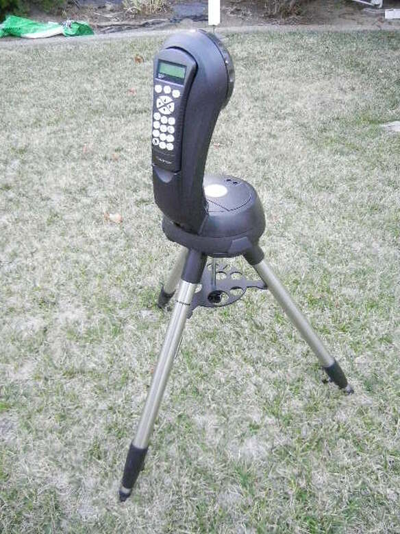 Celestron Single Fork SE Alt-Az Mount Celestron Single Fork SE Alt-Az Mount Alt-Az Mounts Just as SCTs are very popular for EAA, Alt-Az mounts are also popular. Alt-Az (Altitude-Azimuth) mounts do not track the rotation of the earth like Equatorial (EQ) mounts do. EQ mounts have two axes of rotation called Right Ascension (RA) and Declination (Dec). EQ mounts must be polar aligned so that the RA axis, also called the Polar Axis, follows the earth's axis of rotation. This is done with a procedure called Polar Alignment (PA) in which the elevation of the mount is set to the local latitude while the Polar Axis is carefully aligned with the north celestial pole. By doing this the mount rotates about its RA axis so that it matches the earth rotation to keep objects centered in the field of view (FOV). This allows for long exposures of up to many minutes determined by the quality of the mount and the precision of the PA. While an Alt-Az mount also has two axes of rotation and motors on each axis to find and track objects in the night sky, it cannot exactly match the earths rotation. The Azimuth axis is defined by the local horizon and the Altitude simply by the height of an object in the sky. There is no latitude adjustment knob to account for the tilt of the earth's axis. Only at the north and south poles will the Azimuth axis of an Alt-Az mount be pointed at the celestial pole and the mount be able to track the earth's rotation. Everywhere else on the surface of the earth, an Alt-Az mount can keep a star centered in the field of view, but it cannot prevent the surrounding stars in the FOV from appearing to rotate around the central star. This field rotation can cause objectionable elongation in the appearance of stars in images depending upon how long of an image exposure and where in the sky the object is located. The typical rule of thumb is that exposures must be limited to less than 30seconds unless the object being viewed is nearly due east or due west to avoid star trailing or elongation. The actual details are much more complicated and can be found on this web site here. Despite this, Alt-Az mounts work very well for EAA since the trend in recent years has been to take short exposures, much less than 30seconds, and use software like SharpCap to stack successive image frames in real time to give images with an effective exposure of minutes of longer without star trailing. Despite its limitation in following the earths rotation, Alt-Az mounts have several advantages for EAA compared to EQ mounts. First, Alt-Az mounts are less expensive than their EQ counterparts. Also, Alt-Az mounts are typically lighter than EQ mounts for the same load capacity which makes them easier to transport, whether from inside the house to the back yard or to a distant dark site. Finally, since an Alt-Az mount cannot be Polar Aligned, it is much easier and faster to set up a telescope on an Alt-Az mount and get started viewing objects in the night sky. Alt-Az SCTs The combination of SCTs on Alt-Az mounts are now very popular for EAA and come in a number of different sizes and configurations. These are some of the least expensive telescope setups for SCTs. You can get a Celestron Nexstar 5SE SCT (available from High Point Scientific, Agena Astro or Amazon) on an Alt-Az mount for $936, while the Celestron Nexstar 6SE (High Point Scientific or Agena Astro or Amazon) is only slightly ore expensive at $1099 and the Nexstar 8SE (High Point Scientific or Agena Astro or Amazon) is $1600 as of this writing. Celestron also offers a better mount in its Nexstar Evolution series (High Point Scientific, Agena Astro) which is available with a 6" SCT for $1679, an 8" SCT for $2199 and a 9.25" SCT for $2849. The Evolution mount offers integrated WiFi so that the scope can be controlled wirelessly from a phone or tablet, it includes an internal rechargeable Li battery which should last all night long, has improved gears for better tracking and other improvements like manual clutches, etc. The larger the aperture the greater the magnification of the image, but also the more the telescope weighs. The field of view (FOV) of a 6" SCT is 2.46X larger than the FOV of a 9.25" SCT at the same f-ratio so more of very large objects like M33 can be viewed in the smaller SCT, but more detail will be seen in smaller objects like M82 with the 9.25" SCT. The weight difference between an 6" SCT and an 8" SCT is small with the former weighing just 10lbs and the later 12.5lbs. But, at 20lbs the 9.25" SCT weighs twice that of the 6". On the other hand the Evolution mount/tripod weights only 33% more at 28lbs compared to the SE mount/tripod at 21lbs. The SCTs discussed above are Celestron's standard optical tubes. They also make their Edge series of optical tubes (High Point Scientific, Agena Astro) which have additional optical elements in the baffle tube which is designed to give a flatter FOV so that stars are more pin point from center to edge. These are offered in 8" and larger OTAs and come at a premium price with the 8" Edge OTA costing ~$300 more than the non-Edge version and the 9.25" version costing ~$1500 more. If you objective is to also do traditional astrophotography you should seriously consider an Edge version OTA. On the other hand, if you only plan to do EAA the added expense of an Edge OTA is not so clearly justified. Celestron does not offer an SE or Evolution mount with an optical tube larger than 9.25" because the weight of the larger OTAs is too great for these single arm mounts. If you want a larger OTA on an Alt-Az mount you must choose a dual arm fork mount like Celestron's CPC series (High Point Scientific, Agena Astro) with 8" to 11" OTAs. With dual arms these telescopes come with built in GPS, improved drive gears, a heavy duty mount, an auto-guider port, clutches and Periodic Error Correction (PEC) capability. The dual fork telescopes come at much higher cost with the CPC8 at $2600 compared to $2199 for the 8" Evolution. But an even bigger difference is found in the weights, exacerbated by the fact that the OTA is permanently attached to the mount in this design. The CPC8 mount/OTA is 42lbs while the tripod is 19lbs. This compares to 12.5lbs for the 8" OTA and 28lbs for the Evolution mount which makes the SE and Evolution designs much easier to transport and set up compared to the CPC design. Meade does not offer single fork SCTs but they do offer dual fork versions. They only offer these in their ACF (Advanced Coma Free) version of optical tube similar to the Celestron Edge. The 8" ACF sells for $3000 and comes with built in GPS, and over-sized mirror, PEC, and more. Meade offers versions all the way up to OTAs of 16". 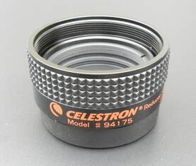 Celestron 6.3X SCT Focal Reducer Celestron 6.3X SCT Focal Reducer Focal Reduction with SCTs As I mentioned in the beginning, the ability to use SCTs at multiple focal ratios is what makes them so versatile and ideal for EAA. Natively SCTs are f/10 which results in very high magnification, especially with cameras using a small chip. For instance, an 8" SCT at f/10 has a focal length of 2000mm. When used with the low cost ASI224MC camera which has a chip diagonal of 6.1mm the magnification is approximately 2000/6.1 = 328. Such high magnification not only means that only the smallest DSOs will fit in the field of view, but that it can be very hard and frustrating to locate the object to begin with. In addition, the exposure times needed to see detail may need to be very long. For these reasons, EAA is most commonly performed at focal ratios of f/2 to f/7 to obtain a combination of wide field and fast optics. Focal reduction is fairly straightforward requiring that a focal reducer be placed between the telescope and the camera. To obtain the specified focal reduction ratio the camera must be placed at the correct distance from the back of the focal reducer according to the manufacturer's specification, usually within a couple of millimeters. If the camera is too close, the focal reduction will be less and if it is too far, the focal reduction will be more. Also, if the spacing is off by too much it may result in vignetting and other types of image distortions. Adapters are available to achieve the correct spacing and spacers in various sizes can be used to fine tune the spacing. For instance, Celestron has a series of T Adapters designed for each of their different OTAs including Edge and non-Edge designs. 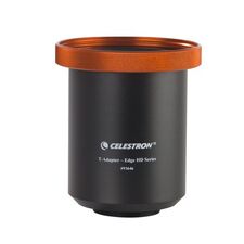 Celestron's Edge Series T-Adapter Celestron's Edge Series T-Adapter There are many focal reducers on the market but not all are designed to work with SCTs. Celestron offers a 0.63X focal reducer (High Point Scientific, Agena Astro or Amazon) for their standard OTAs and a 0.7X reducer for the Edge OTAs (High Point Scientific , Agena Astro) to reduce the focal ratio down to f/6.3 and f/7 respectively. You can also get the Starizona Night Owl reducer for 0.4X reduction ) or the Optec 0.33X focal reducer (High Point Scientific) to produce an even lower focal ratio of f/3.3. All of these are both focal reducers and field flatteners which improves the sharpness of the stars from the center to the edge of the FOV. Since EAA is not meant to produce the high quality images sought by astrophotographers, one can even use a generic 0.5X focal reducer (High Point Scientific, Agena Astro, or Amazon) to get down to a focal ratio of f/5. These come in both 1.25" and 2" versions and are much cheaper than the focal reducers from Celestron, Starizona and Optec. If one is not terribly concerned about vignetting it is also possible to stack focal reducers to achieve an additional focal reduction such as stacking two 0.63X reducers to get a focal ratio of ~f/4. HyperStar While the HyperStar adapter(High Point Scientific) is a field flattener and not actually a focal reducer, it does enable the Celestron SCT focal ratio to be reduced from f/10 to ~f/2. The Hyperstar is a compound set of lenses which replaces the secondary mirror on the front of the OTA. Just unscrew and remove the secondary mirror and screw the HyperStar in its place. The camera is then screwed into the back of the HyperStar adapter so it is looking directly at the primary mirror which has a focal ratio of between f/1.9 to f/2.2 depending upon the aperture of the OTA. Camera cables such as the USB cable for camera control and image capture along with a power cable if camera cooling is used are routed from the front of the OTA to the back. They typically do not cause much interference in the image. Many older model OTAs are not compatible with the HyperStar attachment so check before you buy. Also, be careful not to overtighten the HyperStar onto the corrector plate as it can become frozen in place as it did on my C14 requiring removal of the corrector plate to get the HyperStar adapter off. Hyperstar speeds up the optical system dramatically with required exposures reduced by the square of the ratio of the native and HyperStar focal ratios, or (10/2)^2 = 25 times. The effect is dramatic. In addition the reduction in focal ratio greatly increases the FOV by a factor of 10/2 = 5 which makes HyperStar great for viewing very large DSOs like M33, the North American Nebula, etc. 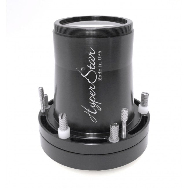 Starizona HyperStar Adapter Summary
EAA with an SCT on an Alt-Az mount is becoming increasingly more popular. The relative low cost of such a setup puts it in the reach of many more people interested in astronomy. Also, these setups tend to be fairly light in weight making them easy to move around without disassembling everything each time you want to have an observing session. And, perhaps, most importantly, the versatility of an SCT on an Alt-Az mount is the biggest attraction. Links are Affiliate links from which I can earn commissions at not cost to you. If you would like to support my web site and its content please consider using my links when ordering products. A good focus is critical to achieving the sharpest details in an image viewed through a telescope whether using an eyepiece for visual observation or a camera for EAA or astrophotography. Because the human eye is capable of focusing over a wide range of distances it is not difficult to achieve a satisfactory focus for visual work simply by adjusting the focuser until the image looks sharpest through an eyepiece. Our eyes can adjust to slight focus offsets or changes in focus with temperature without much difficulty. But for astrophotography or EAA the Critical Focus Zone (CFZ), or distance over which focus is limited by seeing, tube currents, diffraction, can be a fraction of a mm and a camera cannot adjust for deviations from this like the human eye. The CFZ is defined by equation below and depends upon the focal ratio of the telescope and the wavelength of light observed: CFZ = 4.88 x (f-Ratio) ^2 x L where the CFZ is given in microns and L is the wavelength of light in microns. Since L doesn't change much over the range of wavelengths we observe (~0.4 to 0.6 microns) we can use the wavelength for green light, 0.5 microns. For a telescope at f/10 we have: CFZ = 4.88 x (10)^2 x 0.5 = 244 microns while for f/2 (for example using Hyperstar on a SCT) we have: CFZ = 4.88 x (2)^2 x 0.5 ~ 10 microns As you can see, the CFZ is not only very small (244 microns = 0.244mm), it reduces dramatically with focal length because the light cone becomes much steeper at shorter focal lengths thereby compressing the distance over which focus can be achieved. You can see how challenging achieving a sharp focus can be at very short focal lengths. This is why focusing aids are critically important for EAA and astrophotography. Rough Focus While focusing by eye is not sufficient for EAA it is at least good enough for an initial rough focus. To make life easier in the dark it is a good idea to focus during the day time using a distant object like a power pole or tree. This can save a lot of frustration later since one can be centered on a star but not even know it because the light from a badly out of focus star is spread out so much as to be nearly invisible. If like me you do not have sufficient line of sight from your backyard to a distant object for focusing you can use the craters on the moon to obtain the sharpest possible image. If the moon is not visible but Jupiter or Saturn are, another good method is to adjust the focuser until the planet's moons become visible. But this method will have to wait until the sky is dark. Likewise, rough focusing at night can be achieved by observing a star cluster and adjusting the focuser until the number of stars in is maximized. To simplify the process for future nights, make a note of the number of turns from full clockwise or full counter clockwise rotation of the focuser needed to achieve focus. Do this for each optical configuration such as at each focal ratio for your telescope. This way, you will only need to do this once and will be able to quickly achieve rough focus with your telescope in any optical configuration at night without wasting time or getting frustrated. 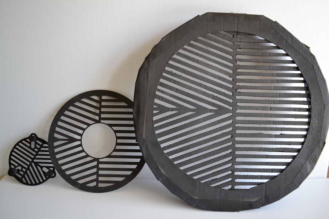 Commercial Bahtinov masks (5" refractor, 9.25" SCT). Homemade mask for a 14" SCT 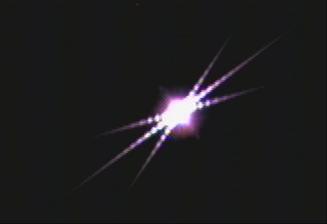 Focus using a Bahtinov mask Focus using a Bahtinov mask Mechanical Focus Aids To achieve the best possible focus, one or more focusing aids are necessary. The most common and simplest is a focus mask. Focus masks of one form or another have been around for quite some time. In 2005 Pavel Bahtinov invented what has become the premier and most widely used focusing mask. This mask consists of a set of three grids etched into a thin plastic sheet which, when placed in front of the entrance to the optical tube, creates a diffraction pattern from the light passing through it. The diffraction pattern consists of an "X" with a vertical line passing through the "X". Precise focus is achieved by adjusting the focuser until the vertical line bisects the "X". The vertical line will move left or right of the center of the "X" as the focuser is moved in and out of focus. A point source such as a star is required to create the diffraction pattern. Use a bright star and/or an exposure of 1-2 seconds to obtain a bright and large diffraction pattern for greater sensitivity. Also, use the camera's zoom feature to magnify the diffraction pattern to achieve the best sensitivity. Bahtinov masks are readily available in sizes to fit most telescope apertures and even come with a center cut-out to accommodate the secondary mirror on an SCT. Many make their own Bahtinov masks as I did meticulously cutting out the pattern in a piece of cardboard for my 14" SCT when I could not find a ready made one at that size. A thin but rigid plastic sheet is a better choice, but my cardboard Bahtinov mask lasted many years until I sold the 14" SCT. Most telescope focusers have a rough and fine focus knob to help achieve a sharp focus. If the focuser that comes with your telescope does not have a fine focus it may not have sufficient sensitivity to achieve the desired sharp images and may need to be replaced with an after market focuser. This is especially true for SCTs which do not have a fine focusing control. There are a number of manual fine focus replacements from companies like Starlight Instruments which are made specifically for SCTs. Also, JMI sells motorized focusers for SCTs which can be controlled by a hand control or via a computer. Both Celestron and Meade provide motorized focusers with fine adjustment control which can help to achieve sharp focus. 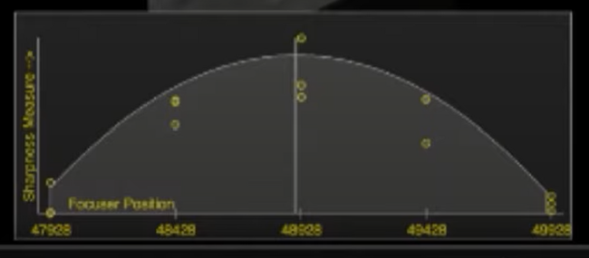 TSX @Focus3 focus curve TSX @Focus3 focus curve Automated Focusing
Since EAA entails the use of a camera and, most likely, software to operate the camera, automated focusing is an excellent way to go. There are many different software available for automated focusing either as a stand along function or as a utility in a larger software suite. FocusMax is a stand alone software which automatically adjusts the focuser on both sides of focus to obtain a V-Curve from two intersecting lines which define a precise focus where the lines intersect. FocusMax uses the Half-Flux Diameter (HFD) to determine the best focus position. The HFD is defined as the diameter of the circle containing half of the star light (flux), which is spread out due to the Gaussian nature of starlight caused by seeing. The smaller the HFD the better the focus and the better the seeing. Since FocusMax connects to and automatically adjusts the focuser, an electronic focuser which can be recognized and controlled by the software is required. A manual focuser will not work in this case. @Focus3 is an excellent focusing utility in The Sky X software. Like FocusMax it requires an electronic focuser which is connected to The Sky X software and @Focus3. It uses the Full Width at Half-Maximum to determine the best focus position. Much like FocusMax, @Focus3 adjusts the focuser on both sides of focus to generate a curve of light intensity versus focuser position. But instead of a V-Curve it produces a bell-shaped curve. Measurement of the width of the curve at half the maximum height defines the FWHM which is then used to find the peak of the curve for the best focus point. Many EAA'ers use SharpCap for real time viewing, live stacking and on the fly processing. SharpCap offers 6 different focus utilities. There are 3 different utilities for deep sky objects, two of which use the FWHM metric to define the best focus. One uses measures the FWHM on a single star and the second obtains an average FWHM on multiple stars in the field of view. The third deep sky focus utility requires a Bahtinov mask and determines the best focus at the point where all three lines created by the diffraction pattern intersect. SharpCap generates a focus score for each focusing utility with the best score giving the best focus. There are also 3 different focusing utilities optimized specifically for planetary viewing which derive scores using measurements of contrast or detail in the image to generate a focus score. SharpCap's focusing utilities can be used with a manual focuser or with an electronic focuser controlled by SharpCap. In either case, the observer adjusts the focuser either by hand or through the SharpCap software. Unlike FocusMax and @Focus3, the process is not completely automated but still works quite well. Thermal Effects As the night air cools, the telescope tube will shrink causing the telescope to go out of focus over time. This is especially true for an Al tube compared to a graphite tube. For this reason it is important to refocus throughout the night. One technique is just to refocus at a fixed time interval such as every 30 minutes which can be done manually or automatically if the right software is used. A more sophisticated method is to use a temperature sensor connected to software to automatically refocus for every half a degree change. Summary Achieving the best possible focus need not be difficult nor expensive. For those wanting simplicity a Bahtinov mask is the way to go. For those wanting automation there are many electronic focusers with compatible software which can make the process practically invisible to the user. Obtaining and maintaining a sharp focus throughout a viewing session will insure the best possible images and the most detail limited primarily by the seeing conditions. 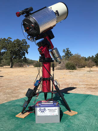 Whether you are doing astrophotography, Electronically Assisted Astronomy or traditional visual observations it is important to understand the difference between a Polar Alignment (PA) and a GoTo Alignment and how to correctly perform each. PA requires aligning the right ascension (RA) axis of the mount to the north celestial pole. This keeps a star or other target centered in the field of view as the earth rotates on its axis. Since Alt-Az mounts have Altitude and Azimuth axes instead of RA and declination (Dec) axes, a PA is not possible with an Alt-Az mount. On the other hand, both EQ and Alt-Az mounts can be GoTo aligned. The GoTo alignment creates a model of the sky so that the mount can slew to, i.e. "GoTo", objects on command and put them within the field of view every time. This makes it much easier and faster to find objects, especially at high magnification. GoTo Alignment A GoTo Alignment requires providing the mount with enough information to build a model of the night sky. Every motorized GoTo mount will have its own alignment routine but the basic principle and inputs are the same. Inputs include accurate information on the date, time and geographic latitude and longitude to start. Next, the telescope will need to be roughly Polar Aligned by leveling the mount and pointing it's RA axis as accurately as possible toward the north celestial pole using a compass or Polaris as described in the PA section below. Using the hand control (or software emulation) you will need to slew to 1 or more stars or solar system objects, center them in the field of view of an eyepiece or camera with the hand control and then confirm that when each is centered. The mount uses the RA and Dec data for these objects, along with the date, time and location to generate a sky model. The concept is simple and the process is straight forward and only varies slightly from mount vendor to vendor For example, Celestron's GoTo mounts offer several different alignment options. The Solar System Align option simply requires that the mount be slewed to a visible solar system object like the Sun, Moon or a planet. Once the slew has been completed, the hand control is used to center the object in the field of view and then confirmed with the hand control. A Solar System Align is useful when one wants to do the alignment during daylight, but is not as accurate as a multi-object alignment. A One Star Alignment is similar except a star instead of a solar system object is used which is more accurate than aligning on the Sun or the Moon since a star is a pinpoint object which provides a higher a degree of accuracy when centering it in the field of view. A still more accurate alignment is obtained by using the Two Star procedure which is identical to the One Star alignment except that two stars are used instead of one. At the end of the Two Star alignment, the hand control will ask if you want to add one to four calibration stars. The calibration stars compensate for any offset of the telescope's axis to the mounts declination axis. The Two Star + Four Calibration Stars will provide the best GoTo model and has the greatest chance of putting objects in the center of the field of view at higher powers than the other methods. It simply adds 4 more stars on the other side of the meridian to center in the field of view. Other mount manufacturer's like Meade and Synta (Sirius, Atlas) use an identical procedure with One, Two, or more stars for alignment but do not add the Calibration Star correction. Since the GoTo alignment will be disturbed if you need to adjust the mechanical axes of the mount for the PA procedure discussed below, the GoTo alignment will most likely need to be repeated after the PA. So why not do the PA first and then the GoTo alignment. Because having a basic GoTo alignment prior to the PA is helpful so that the mount will slew to the star being used during the PA process. Unless you have a good handle on the names of the stars, you might not be able to locate the PA star easily, especially at a dark site, if the mount does not put it close to the field of view. Therefore, do the simplest possible GoTo alignment before the PA and then come back with the 2 + 4 star alignment after if using a Celestron EQ mount.  Celestron's Star Sense AutoAlign Celestron's Star Sense AutoAlign The GoTo alignment procedure for an Alt-Az mount is pretty much the same using as few as 1 star and as many as 3 stars for a more accurate alignment. Some Alt-Az alignment routines do not even require that you know the names of the stars. For instance, Celestron's Sky Align routine only requires that you slew to 3 bright objects (stars and or planets) in the sky one at a time and center them in the field of view. The 3 objects should be chosen to be as far apart as possible to provide greater precision. Once completed, the mount build the sky model and let you know the names of the 3 objects you chose. This is very convenient if you are not yet familiar with the stars in the sky. There are other routines where the mount provides a list of stars for you to pick the ones to slew to, allowing alignment with only 1 or 2 stars. Meade's AudioStar alignment procedure requires that the telescope be set to the "home" position first with it pointed north with the optical tube level. Some higher end Meade telescopes can automatically find north and the home position. AudioStar then slews to two of the brightest stars in each location so that it is easy for you to find them and center them in the field of view. There are also hardware solutions like Celestron's Star Sense AutoAlign, which can both automate and speed up the GoTo alignment process. Star Sense works only with Celestron mounts and contains a small camera and software. First time setup requires attaching it to the mount and aligning its axis to the telescope's optical axis. Star Sense then connects to the mount and slews to different parts of the sky taking images which it plate solves to determine the RA and Dec of each image. From this information it is able to build a GoTo model of the sky. 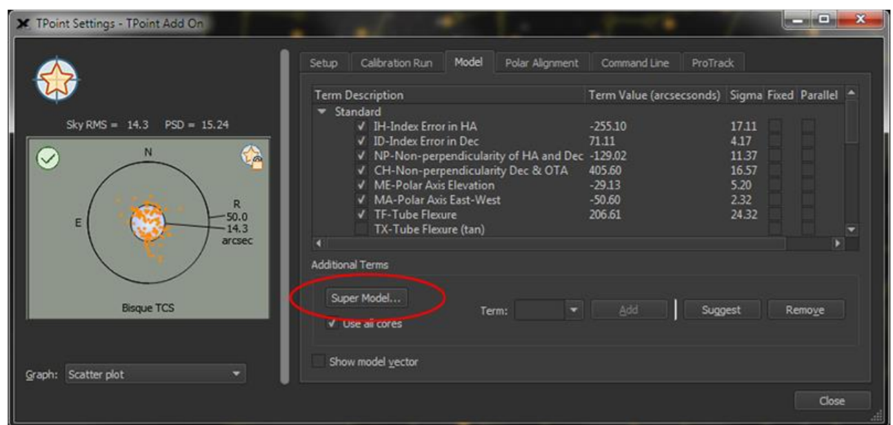 T-Point Alignment and Super Model Window. Taken from the manual. T-Point Alignment and Super Model Window. Taken from the manual. If you use The Sky X (TSX) from Software Bisque you will have access to a separate software algorithm called T-Point which generates one of the most accurate GoTo models and uses a process that is easily automated. T-Point requires a minimum of 6 points and can handle a maximum of 500 points. T-Point can be run manually by using the hand control to slew to and center each star one by one and confirming such to the software. If using a camera it is better to use the automatic mode. In this case, a map is first generated of the points to be used which should be distributed across the night sky While T-Point requires a minimum of 6 points, most will use 30 or more points for greater accuracy. Once the points have been generated, TSX will automatically slew to one point after another, take an image, and plate solve the image to determine the exact RA and Dec at the center of the image. Once all the points have been collected, regardless of whether this is done manually or automatically, a multi-parameter model of the night sky is generated and the mount is ready to put objects close to the center of the field of view every time. Obviously this process will take longer than doing an alignment with 1 to 6 points, but the automated process can do as many as 60+ points in 20 to 30min and the resulting model will be a much more precise GoTo model. Unlike the other GoTo procedures, the T-Point alignment does not need to be repeated after using T-Points PA procedure. Polar Alignment During a PA the right ascension (RA) axis of a telescope mount is aligned with the rotation axis of the earth so that a celestial object in the field of view will stay centered over time. Without a PA, the object will drift across the field of view. This is not generally a problem for a visual observer but for those doing astrophotography it will cause stars to become elongated in an exposure of only a few tens of seconds. The better the PA achieved, the longer the unguided exposure possible to maintain pin point stars in the image. This of course, also depends upon the quality of the mechanics in the mount being used which is why it is often said that the mount is the most critical component in the astrophotography setup. For EAA with live stacking, things are more relaxed, but it is still true that the better the PA the longer the exposure possible and the longer one can stack images before field rotation becomes an issue. There are many different ways to achieve a PA, some software based and others hardware based. Let's review some of these. Rough Polar Alignment A rough PA is good enough for visual work but not for EAA and astrophotography. However, it is a necessary starting point for both an accurate GoTo and PA. First, point the mount in the direction of north and level it. Do this without the telescope attached so that it is much easier to make the necessary mechanical adjustments especially if using a heavy telescope. It is not necessary to have the mount perfectly level, but the more accurately you level it the easier the rest of the procedure will be. Use a compass to find north but be careful to stand back away from the mount since the metal in the mount will affect the accuracy of the compass. Also, be aware that magnetic north (where the compass needle points) is not the same as true north (Earth's north pole). You will need to offset the position of the mount by the local magnetic declination of your location which you can look up here. For example, the magnetic declination of Adin, CA, where the Golden State Star Party is held, is 13deg 43min East (positive), which means that true north is 13deg and 43min East of where the compass needle points. It is helpful to make certain that the Azimuth adjustment is centered leaving you plenty of room to make an adjustment to the east or west as needed during the fine tuning of the Azimuth during the accurate PA step later. Next use the Altitude adjustment bolts to raise or lower the mount's altitude to match your latitude. Now mount your telescope. If your telescope has the option of using a Polar Scope you can get a more accurate rough PA by sighting through the Polar Scope and adjusting the Alt. and Az. mechanical bolts until Polaris is positioned in the field of view according to a mobile application like this one which will show where Polaris should appear in the reticle depending upon the time and your location. However, a Polar Scope will not give a good enough PA to avoid the accurate PA process so many just skip this complication and move from the rough mechanical alignment to the accurate PA. Accurate Polar Alignment The rough PA needs to be followed by one of the following procedures to obtain an accurate PA. Drift Alignment The drift alignment method is considered the gold standard for PA because it measures the actual drift of a star over time. This allows one to make continual adjustments until the drift has been reduced to a level which will not cause noticeable drift during an exposure. First locate a star close to the celestial equator and the meridian and center it in the cross hair of an illuminated reticle or the center of a camera image. The closer the star is to this location the greater the sensitivity but it is ok if a convenient star is off in RA by a bit. Next, observe the star for a length of time approximately 5X as long as your longest expected exposure and watch to see which direction the star drifts. If it drifts north, adjust the Azimuth axis so that it points more to the east. If it drifts south, adjust the Azimuth axis so that it points more to the west. You tell determine which way is north or south ahead of time by moving the telescope to the south and watch the stars move which will be to the north. Ignore any drift of the star to the east or west for now. Repeat this process until you have reduced the drift to a negligible amount. Now locate a star near the celestial equator and on the eastern or western horizon about 20 to 30 degrees of altitude. Center it in the field of view and watch for drift over the same 5X time period. If it drifts north, lower the mount's altitude. If it drifts south, raise the mounts altitude. Repeat the process until the drift is negligible. The drift alignment method is tedious and time consuming when first mastering the process but it gives direct visual feedback on the PA achieved. There are many tutorials on line which explain the drift alignment method in detail. There are also many software applications which are designed to simplify the drift alignment method, such as PHD2 's drift alignment tool. 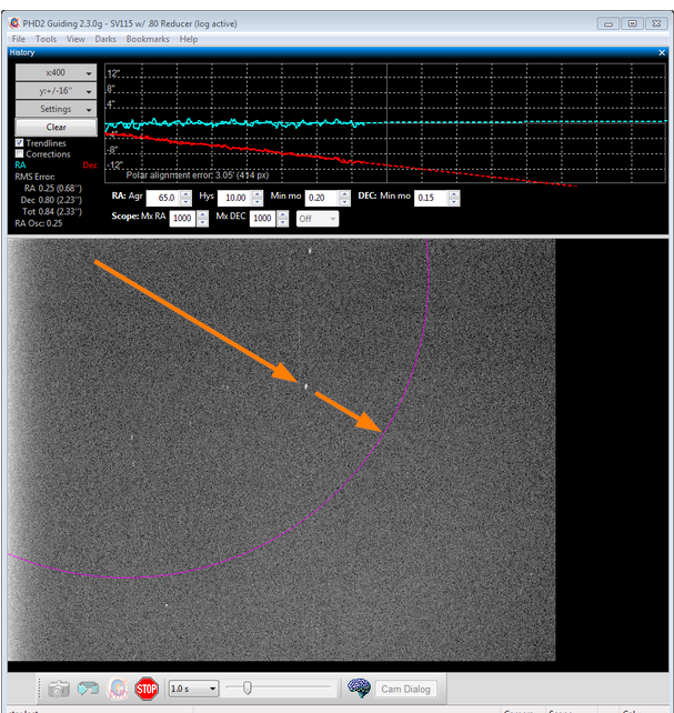 PHD2 drift alignment tool. Image taken from the manual. T-Point If you use The Sky X (TSX) you will have access to a separate software algorithm called T-Point which simultaneously performs a PA and a GoTo alignment. The first part of the procedure which generates a GoTo model has been described above. Once this has been completed, the next step is to begin the accurate PA routine. TSX provides a list of stars for you to choose one. Once chosen the mount slews to the star and you center it in the FOV with the hand control. Then TSX moves the mount to where the star should be if accurately PA. Next you re-center the star using only the manual controls for Azimuth and Altitude. Once completed, TSX takes into account the adjustments made and adjusts the GoTo model so that it does not have to be repeated. 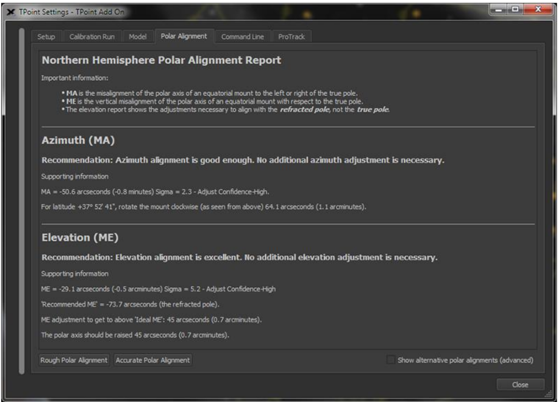 Celestron's All Star Polar Align Celestron has a PA routine called All Star Polar Align which does not require the ability to see Polaris. In fact, like the drift alignment method, greater PA sensitivity is achieved by picking a star near the intersection of the celestial equator and the meridian. The process will be easier if a GoTo alignment has been performed first so that the mount is more likely to put the star in the field of view. It is a good idea to have a finder, either unity of 50X, to help locate and center the star if it is not in the field of view. After the slew the star should be centered at high power and then verified with the hand control. The mount will then slew to the position where the star should be if accurately polar aligned. Next, using only the mechanical adjustments for Azimuth and Altitude, re-center the star in the field of view and confirm with the hand control. The mount will now be PA. It will be necessary to re-do the GoTo alignment since the mount has been adjusted from its position during the original GoTo alignment.  SharpCap Polar Alignment Screen taken from the manual SharpCap Polar Alignment Screen taken from the manual SharpCap Many people find the Polar Alignment routine in SharpCap software to be easy, fast and accurate. It works by taking two pictures, one around the pole and the other with the RA axis rotated 90 degrees. SharpCap then plate solves both images and determines the position of the celestial pole and the center of rotation of the RA axis. SharpCap will show how far off the PA is in degrees/minutes/seconds and give directions for which way to adjust the RA and Altitude axes. The process is repetitive until the user has decided that the offset from the celestial pole is at a minimum. You will need the pay version of SharpCap for the PA routine but the cost is rather minimal. QHY's Pole Master QHY has a hardware solution for accurate PA which, like Celestron's Star Sense, attaches to your mount and has a camera and software. QHY's Pole Master connects to you computer and takes an image of the sky around Polaris. It plate solves and then requires that the mount be rotated by ~15 degrees with the hand control and takes another image from which it determines the axis of rotation. Fromm this it will determine the adjustments you need to make in the Az and Atl mechanical knobs. So the methodology is the same as with Sharpcap except it uses a separate hardware device. Summary
So it should be clear by now that a GoTo and a Polar Alignment are not the same. You can have one but not the other such as with an Alt-Az mount. If you are using an EQ mount you will want to make sure that you perform both alignments so that you can quickly locate objects and then track them over the length of you chosen exposure without objectionable star trailing. For the beginner, these may sound daunting, but with a little practice over a couple of nights under the stars, both methods will become second nature. OPT links are Affiliate links from which I can earn commissions on purchases. In this edition of my "EAA for Beginners" series we will discuss the different software available today for camera control and live image enhancement. The most commonly used ones are SharpCap, ASILive, Starlight Live, Infinity, ToupSky, MallincamSky, RisingSky and Miloslick. It is impossible to go through each of these in detail in a short artical like this. Complete details for each package can be found in its respective user manual. Instead, this will be an overview of the main features which are necessary or very useful for EAA followed by a brief discussion of some unique features of each specific software package without going into great detail on any of them. The objective is to give you the big picture so that you can zero in on one or two of the applications and do more detailed homework to decide which one is best for you. In a later edition, I will do an in depth review of SharpCap since that is one of the most used applications, the one with the most features, and the one I use most of the time. While I have also used Starlight Live and Miloslick I prefer SharpCap.  Mallincam Xtreme OSD Main Page Mallincam Xtreme OSD Main Page The First EAA Software In the earliest days of EAA with analog video cameras like those from Stellacam and Mallincam, camera settings were controlled by the On Screen Display (OSD) as shown in the picture below. To modify the settings, 5 tiny buttons on the back of the camera had to be engaged to navigate through the menu as one watched the OSD on a video monitor. This was very cumbersome for many reasons including the difficulty of manipulating the buttons in the dark and in the cold when wearing gloves. Eventually, wired hand controls became available but all these did was effectively move the buttons away from the back of the camera as far as the cable would reach. Useful, but still all the difficulties of buttons and an OSD. Also since these astronomy cameras were modified security cameras, navigating the OSD could be confusing as there were multiple pages and sub-pages with control settings designed and named for the cameras' original purpose, video surveillance, with names like "Sense Up", "ALC", "ELC", "BLC", "Sync", etc. Huh? Furthermore, the control software was designed to be set once and seldom, if ever, changed whereas for astronomy, the settings needed to be adjusted on the fly to optimize the view for each target object. Scrolling through screen after screen to find the parameter you needed to change using the tiny buttons was a pain! After a while folks like Stephane LaLonde and Steve Massey developed software for the Mallincam and GSTAR line of cameras with an astronomy minded user interface which translated the camera controls into much more friendly astronomy jargon and organization. This greatly simplified control of the camera settings while viewing images on a computer and changing settings from the computer but did nothing to allow the user to enhance the quality of images beyond the camera's native capabilities. One had to rely on camera exposure, gain, gamma, cooling and other features built into the camera itself to enhance live view images.  Camera Controls from the SharpCap manual Camera Controls from the SharpCap manual Today's EAA Software Today's EAA software consists of similar camera control capability like that in Stephane's and Steve's earlier software, but it also includes a wealth of live image enhancement features. There are many different software available today for use in EAA with most developed to work only with a specific brand of camera. These include software from ZWO (ASILive), Starlight Xpress (Starlight Live), Atik (Infinity), Mallincam Video Cameras (Miloslick), Touptek (ToupSky), Mallincam Digital Cameras (MallincamSky), and Risingcam (RisingSky). The most widely used software for EAA (also works well for traditional astrophotography) is SharpCap which is designed to work with most cameras on the market today. Today's software consists of two basic elements. First, there is the camera control element which enables adjustment of camera settings which, like Stephane's and Steve's earlier software, makes changing camera setting so much more user friendly, simple and quick. The second element which was missing from the earlier software includes live image stacking, dark frame subtraction, histograms, FWHM measurements, and much, much more. It was this second element which provided a revolution in EAA capabilities early last decade. We will go through the basic EAA software features below starting with camera setting controls. Camera Controls As mentioned above, for EAA the camera settings need to be adjusted depending upon the target object and the sky conditions so all of the applications mentioned above provide the ability to set and adjust all of the typical settings in cameras available today. First and foremost is the image exposure which, depending upon the camera, can be set from sub milli-seconds to infinity. The exposure progress is displayed showing the remaining time left before the image is displayed. Single images or a sequence of images can be viewed on a screen and/or captured to local storage. Images can be saved in a number of different file formats such as FITS, TIFF, JPEG, PNG, etc. Also, a video sequence can also be captured which is useful for lucky imaging of the planets. These are saved as AVI, SER etc. files. All cameras have a gain setting which can be increased to boost the sensitivity of the camera for a given exposure to bring out more detail, or reduced to minimize background noise. Typical cameras today have the ability to combine adjacent pixels into an effectively larger single pixel called binning. Binning increases sensitivity at the cost of resolution. Binning choices are 1 x 1 (native camera resolution), 2 x 2 (4 pixels), 3 x 3 (9 pixels) and 4 x 4 (16 pixels). Also, most cameras today come with the option of cooling the sensor with an internal Peltier cooler attached to or nearby the image sensor. Live Image Enhancement As we said above, the second element of software used for EAA is the ability to manipulate the image in real time which has led to a revolution in the quality and sophistication of EAA images which can now rival long exposure astrophotos. Each of the software packages used for EAA include the basic elements of live image enhancement. Let's go through each of these in a little detail Image Preview A preview of the latest image is shown on the monitor. As each exposure is taken, the latest image replaces the previous one. If stacking is turned on, the image refreshes with each new frame in the stack. The previewed image can be enhanced on the fly by using the white balance, brightness, contrast, saturation, hue adjustments, depending upon which are present. In addition, further image enhancements are possible through histogram controls discussed below. Image Stacking Among all of the technical advances in cameras and software, many would agree that live stacking has done more to enhance the ability of EAA than any of the others. Live stacking adds or averages any number of successive frames together, aligning them to the first frame by translating and rotating subsequent frames in software to align the stars in the image. Live stacking greatly improves the image viewed by reducing the noise and increasing the signal, since random noise from frame to frame is overwhelmed with the fixed signal content in each frame. This makes it possible to see spiral arms and dust lanes in galaxies and brings out faint nebulosity in planetary nebulae. Instead of having to capture many images for post processing the next day as in traditional astrophotography, one can watch the image improve before their eyes as each subsequent frame is added to the stack. Live stacking has made it possible to take and stack many very short exposures of a few seconds instead of taking a single long exposure of several minutes to bring out detail. Using short exposures means that one does not need a mount with high tracking accuracy. No does one need to do a very precise polar alignment as needed for astrophotography. Instead much less expensive mounts and even Alt-Az mounts are highly capable for EAA when live stacking is employed. Of course, there is a limit to the ability to adjust successive images to overlay the original frame if the polar alignment is way off or an exposure much longer than 30sec is used with an Alt-Az mount. Live stacking can only do so much. While all of the applications provide live stacking, they differ in stacking options which they may provide. These include stacking by Summing frames, Averaging frames, Sigma Clipping which discards frames with satellite or airplane trails, and FWHM filtering of frames which discards frames with bloated stars. Histogram The histogram is a graphical representation of the amount of light reaching each pixel. It shows the number of pixels on the vertical axis and the grey scale on the horizontal axis with completely black (no signal) on the far left and completely white (saturated pixels) on the far right. So each point on the histogram curve represents the number of pixels at each level of brightness. One can quickly see if the image is over-exposed as the curve will be shifted too far to the right. This means that stars will look bloated and detail is lost. On the other hand, one can also quickly determine if the image is under-exposed as the curve will be shifted too far to the left so that the background will appear grainy and faint detail will be lost. The ideal histogram will show space between the lower edge of the curve and the left axis and a long tail decreasing to the right. The histogram is a valuable tool which can be used to tease out an improved image live on the display screen. There will be 3 sliders shown at the bottom of the histogram for the black, mid and white level settings. The black slider at the lower left controls the position of the black point (pure black - zero signal) for the image. Moving to the right closer to the peak of the histogram darkens the background. Moving it too far to the right will clip data at the low end causing detail to be lost. The slider to the right controls the position of the white point (pure white - saturated signal). Moving it to the left brightens the image. Moving it too far overexposes the image. The mid point slide is used to stretch the grey scale linearly which helps to bring out faint detail. Some software, like ToupSky and Miloslick provide a feature called Curves, which allows the histogram to be stretched in a non-linear fashion. Curves provides more control over which parts of the image are darkened while others are lightened. Histogram sliders can be adjusted on the fly to improve the appearance of the image on the display in real time, but do not change the settings on the images being captured. 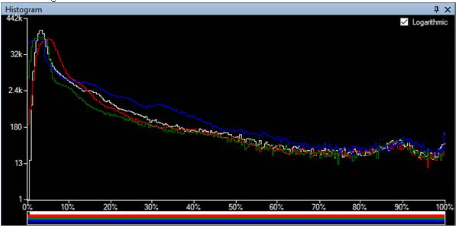 Sharpcap's Histogram taken from the manual Color Balance If a color camera is used the histogram will have one curve each for red, green and blue, whereas for a mono camera there will be a single luminance curve. The color can be balanced by manually adjusting the three histograms so that their peaks coincide. This can also be done in most applications automatically. Dark Frame Subtraction Image quality can be degraded due to noise coming from the camera itself in the form of hot pixels (defective pixels which are always on) and warm pixels (thermal noise). Noise can also come from the electronics in the form of amp glow which is thermal noise from camera amplifier circuits next to the image sensor. Dark frame subtraction is used to counteract these noise sources. A dark frame is taken with the telescope optics covered so that no light gets into the camera. It is important to take the dark frame with the exact same settings (exposure, gain, binning, cooling) as the image (light) frames. Although a single dark frame can be used, it is best to take multiple dark frames and average them together into a single master dark frame. 16 frames is considered a good compromise number of frames. Many who have a camera with cooling build a master dark library with different camera settings during times when they cannot observe (cloudy nights, daytime) so that they preserve precious time on good nights for observing. Flat Frames Some of the software applications allow for flat frames to be captured and used to scale subsequent image frames. Flat frames are commonly used in astrophotography to correct for differences in light intensity across the image plane. Without such correction images typically will appear brighter in the center and darker toward the outer edge of the frame, an effect called vignetting. Vignetting will be exacerbated when strong focal reduction is used. Flat frames are also valuable in eliminating the doughnut appearance from out of focus dust on the optical elements in the light path. Defective or Hot Pixel Removal Many of the software provide the capability to automatically detect defective and/or hot pixels. These are pixels that always appear black or pixels which always appear bright detracting from the overall view of the image. The application detects these pixels and averages the signal from the surrounding pixels so the pixel blends in. FWHM (Image Quality, Focus Tool) Several software provide information about the Full Width at Half Maximum (FWHM) of the stars. This is a mathematical measure of how many pixels a star covers. The less pixels the sharper the star appears. If a star covers too many pixels the stars appear bloated. This may simply be an indicator of too long of an exposure or of poor seeing due to momentary turbulence. The FWHM can be set to trigger an image to be captured only when the FWHM is below a set level. This is useful during live stacking so that only the images meeting the FWHM setting are stacked, improving the overall image quality. The FWHM measurement can also be used as a tool to focus the image. This is done by moving the focuser in and out while capturing the FWHM at several different focus points. Data for FWHM versus focuser position is collected and a curve its fit to the data. The best focus is defined at the point where the curve is at a minimum, i.e. the smallest FWHM and the tightest stars. Misc Controls A number of different features may or may not be available depending upon which software application is used. These include the ability to zoom into a region of the image to get a more detailed view. Image orientation is a feature to rotate or flip the image upside down or left to right which allows the viewer to correct the image orientation which may be reversed due to the type of telescope used. Several of the applications provide a selection of screen overlays such as a cross hairs or grids which can be viewed on top of the image. These can be quite useful for centering an image, performing a polar alignment and measuring separation of objects in the field of view. Overlays may also include text to help label the image and exposure details. Second Screen allows one to place a duplicate view of the image on another screen to be more easily viewed by additional people. 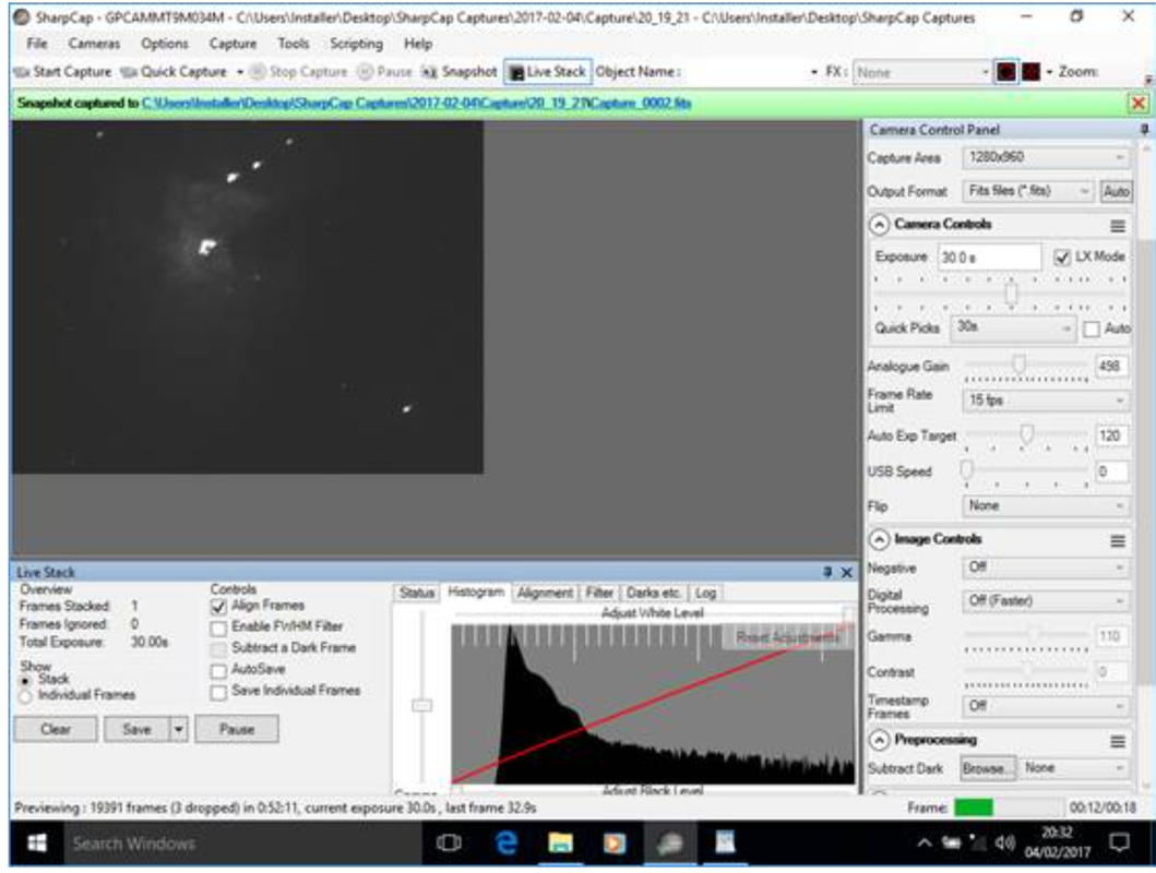 SharpCap's Main Window taken from the User Manual 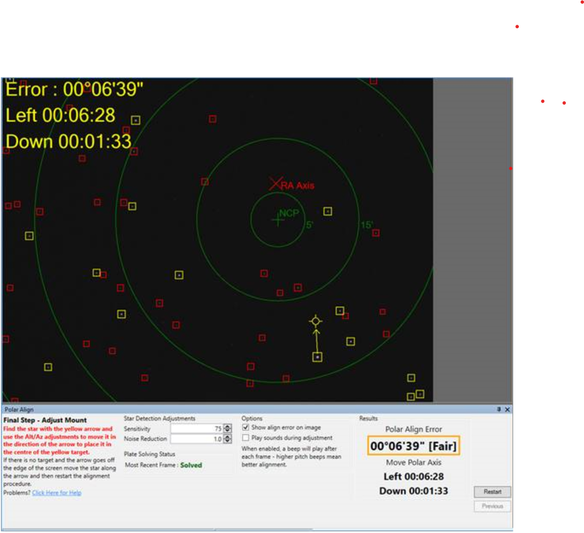 SharpCap Polar Alignment Window taken from the manual SharpCap Polar Alignment Window taken from the manual SharpCap In 2010, Robin Glover created a software program called Sharpcap to improve upon AmCap and similar Webcam viewing software. By 2012 he had modified SharpCap to work with video cameras commonly used for EAA. Not long after, he was among the first to add live stacking capability which immediately made SharpCap a hit with most everyone doing EAA. Today, SharpCap is probably the most used software for EAA, and also one that many astrophotographers use as well. Over the years Robin has added many helpful features to SharpCap which has led to the only complaint that I have heard raised about it. Because it is so feature rich, it presents a steep learning curve. But once mastered, useful features abound. SharpCap comes in two versions. There is a free version which contains all of the essential features for EAA and several extremely powerful additional features. The second version costs a mere ~$19 a year but includes quite a few unique features not available in other common EAA software. An extensive manual is available on Robin's website. SharpCap works natively with many cameras including those from ZWO, Atik, QHY, Starlight Xpress, Basler, Celestron and many more. Also, it works with other cameras which have an ASCOM driver. SharpCap provides support for Ascom focusers, filter wheels and mounts allowing them to be controlled directly from SharpCap rather than through additional SW applications. Before looking at the added features of the Pro version, lets look at some unique features of the free version. Many would agree that the capability to Plate Solve is key among these. With this, an image of the sky is taken and using one of four free Plate Solving tools in the background, SharpCap determines the actual coordinates at the center of the frame and moves the mount to center the telescope at the desired location. Plate Solving is a powerful tool to help located dim objects in the sky or to accurately return to a specific location. The free version of SharpCap also has a Sensor Analysis Tool which can automatically measure the read noise of your camera's sensor versus gain. Another useful unique feature is the ability to utilize one of 6 different Focus Aides including one for analyzing the diffraction image from a Bahtinov mask, another with single or multi-star FWHM analysis, and so on. The pay version of SharpCap adds some useful tools not available in the free version and also not available at this point in any other EAA software. First, it has a Polar Alignment tool which eliminates the need for another SW package or additional hardware to make an accurate polar alignment. Not only that, but the polar alignment routine is simple to use and fast. A Smart Histogram is also available with the pay version which, working with the Sensor Analysis tool, can determine the best exposure and gain to use for the specific sky conditions. The Sequence Planner is another powerful tool in the pay version which automates the process of collecting images allowing the user to set the Planner up and let SharpCap run in an automatic mode. This feature is more of an astro-imaging tool than an EAA tool, but is good to have if there is an interest to do some traditional astrophotography as well.  ASILive Main Window taken from the User Manual ASILive Main Window taken from the User Manual ASILive ASILive is free software from ZWO which only works with ZWO cameras. It is a sub-set of ASIStudio which includes applications for Planetary and Deep Sky imaging, along with a Deep Sky stacking application and a FITS viewer. ASILive is one of the few EAA software that work with Windows, MAC and Linux and iOS. A very limited ASILive manual is embedded in the Help section of the program. Due to the popularity of ZWOs cameras for EAA, ASILive is probably the 2nd most used application for EAA. It has almost all of the features described above and a few additional ones described here including the capability to remove the last frame from a stack using the "Undo Last Sub" command. This is useful if a satellite, plane or cloud passes through an image while live stacking. ASILive also adds Bias Frames to its ability to take Darks and Flats. And, since ASILive is fully integrated with ZWO hardware, it includes the Focuser and Filter Wheel Control for ZWOs own focuser and EFW filter wheel. Most ASILive users fully integrate with ZWO's platform including their ASIAIR hardware for complete camera and equipment control and power.  Infinity Main Window taken from the Manual Infinity Main Window taken from the Manual Infinity Atik's Infinity software is free to download from Atik's web site but only works with Atik cameras such as the Infinity and Horizon cameras. The manual can be downloaded from the Atik web site. The Infinity software is also works with Windows, MAC and Linux and iOS. It has most of the features discussed above but is noticeably lacking dark frame subtraction and flat frame scaling Infinity does have a few features which are unique. There is a Finder Mode designed to facilitate finding deep sky objects by using high gain and short exposures. Images will be noisy but once found, the user can switch to better settings. The Record and Replay Mode allows one to record every FITs image during a session which can be played back later for review or sharing. There is also a Live Broadcast mode which allows for broadcasting a session live view on YouTube or the Video Astronomy Live website. 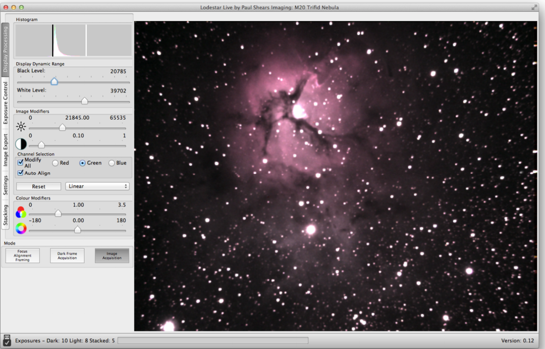 Starlight Live Image Processing Window taken from the manual Starlight Live Starlight Live started out as Lodestar Live, a program created by Paul Shears to allow enhanced live viewing with Starlight Xpress' Lodestar camera. It eventually became part of Starlight Xpress and was renamed Starlight Live. It is free software which only works with SX cameras. At present there is a Lodestar Live manual which is the same as Starlight Live. In addition to most of the features outlined above, Starlight Live includes Non-Linear Stretching of the histogram that changes the contrast of the image, reducing the brighter regions like cores and enhancing the dimmer regions like the spiral arms of a galaxy. It lacks the ability to take Flat Frames. 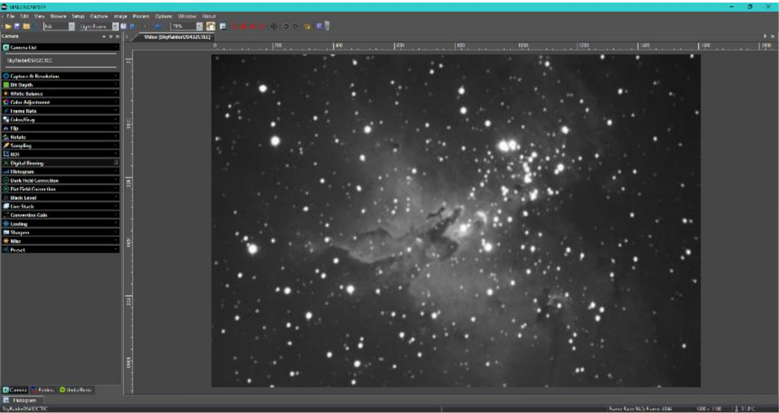 MallincamSky Main Window from the Manual ToupSky, MallincamSky and RisingSky ToupTek is a Chinese company which makes cameras for a number of different applications, including astronomy. They make a line of cameras using the same Sony sensors as everyone else and sell them on AliXpress. ToupTek astronomy cameras have their very own free version of live stacking software that they call ToupSky. Mallincam and Risingcam work with ToupTek to produce cameras for themselves using the same Sony sensors. You will see a significant overlap in camera offerings among these three. Not surprisingly, Mallincam has its own free software called MallincamSky, while Risingcam has RisingSky. If you look carefully at the software manuals you will see that the software features are nearly identical to those in ToupSky, but each software only works with its parent camera supplier. All three of these applications are packed with the basic features described above for EAA along with a few additional features. ToupSky ( and possibly the other two) has Curves which is similar to histogram stretching but allows a continuous stretch along the entire histogram instead of just 3 points which can help to bring out more detail in an image They also include a Sharpen feature to sharpen fine details in an image. 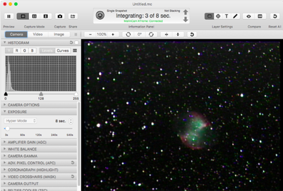 Miloslick Main Window taken from the manual Miloslick Main Window taken from the manual MiloSlick Mallincam Control Bill Koperwhats has developed software designed to work with Mallincam and some generic analog video cameras. Along with Robin's Sharpcap and Paul's Lodestar Live, Bill's software was one of the earliest providing camera stacking and histogram adjustments. It has evolved over the years and now has most of the features discussed above. MioslSlick works with Windows and MacOS. A manual is available on the Mallincam web site. MiloSlick also has a Curves adjustment feature with four adjustments points instead of just three. It also has the ability to Autodetect and Remove Hot Pixels. Frame stacking, however, is limited to no more than 10 frames. But frame stacking also allows for Rolling Frame Stacking which stacks the most recent frames and replaces the oldest frame with the newest in the stack. One of the more unique features of MiloSlick is its High Dynamic Range (HDR) Averaging. HDR allows the user to take images of different exposure times and stack them together into a single image which helps to retain detail in dark regions of an image while bringing out more detail in bright regions of the image. Without HDR viewers have to choose between "blowing out" the bright regions like the cores of galaxies in order to bring out detail in the spiral arms and dust lanes, or, the reverse. MiloSlick also has Sharpening and Smoothing algorithms to further enhance images. Summary There are many good software packages which can be used for EAA. Several are also quite capable for traditional astrophotography as well. The decision as to which to use may come down to whose camera you have as most are designed specifically for particular cameras. Below is a table with a summary of most of the features found in EAA software. As it shows, SharpCap, especially the Pro version is the most feature rich which is why it tends to be the most commonly used. While the learning curve is steep, it has a good manual and there is lots of online support including on the SharpCap forum and from several YouTube tutorials. 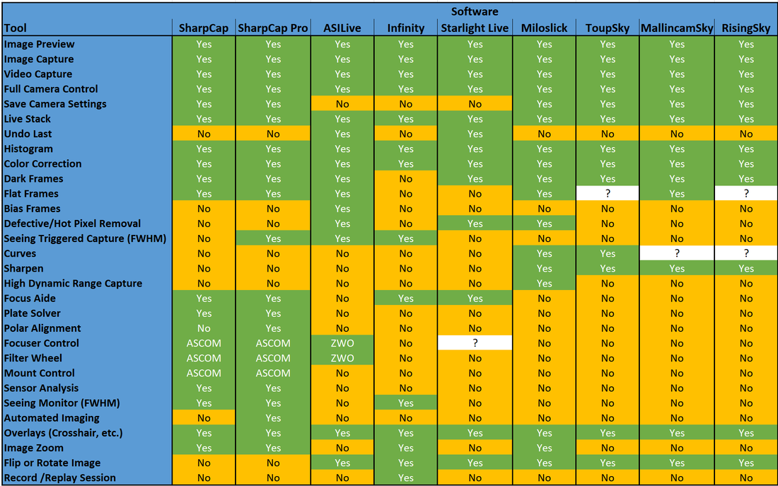 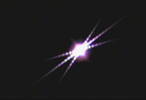 In the first four installments of this series on EAA we have covered the big ticket items needed to get started including mounts, telescopes and cameras. Now we will look at the accessories most necessary for EAA. There are many possible accessories one could use to enhance the EAA experience, but in this installment we will discuss only the ones which are most essential to have right from the start. Of course, there can be differences of opinion as to what is essential and what is optional, but based upon my personal experience and what I see posted by other practitioners of EAA I feel fairly confident that you will find the items below extremely useful. Bahtinov Mask Before an EAA session can begin, even before the telescope can be aligned, it is necessary to focus the telescope. If you have a good view of a distant power pole, tree or similar object you can rough focus on that with an inexpensive wide field eyepiece (EP) like this 32mm or longer focal length example along with a cheap diagonal which may have already been included with your telescope. This is especially helpful if the telescope is way out of focus which can lead to a great deal of frustration. This was the case after I configured my SCT with my 2X Televue Powermate for the recent Jupiter-Saturn conjunction. I find it much harder to use my camera to get back into focus when I am initially far out of focus than using an EP. If you are like me with a backyard that is obstructed from such views you will have to use the moon when it is up, or work with the brightest star visible to make it easier to get close to focus. Once close to focus you will need to fine tune the focus to get a sharp image. If you are using imaging software which has a focus feature like FocusMax or Sharpcap you can use that to fine tune the focus. If not, the best option to assure sharp focus is a Bahtinov mask. Invented by the Russian amateur astrophotographer Pavel Bahtinov, the Bahtinov mask has become the go to tool for astronomers for quick, easy and accurate focusing. Usually constructed with pliable but sturdy plastic it consists of three grids designed to create three angled diffraction spikes for each bright object in the FOV when placed on the front objective of the telescope. Two of these spikes form an "X" while the third forms an "I" through the "X". As the focuser is racked in and out, the "I" shifts from one side to the other. When the "I" bisects the "X" in the center, best focus has been achieved. You can read more about how this works and view a simulation on this Wikipedia page. Once focused, the Bahtinov mask must be removed. If your telescope needs to be re-focused throughout the night, you will have to repeat the procedure each time which is really the only disadvantage of this technique compared to software focusing. 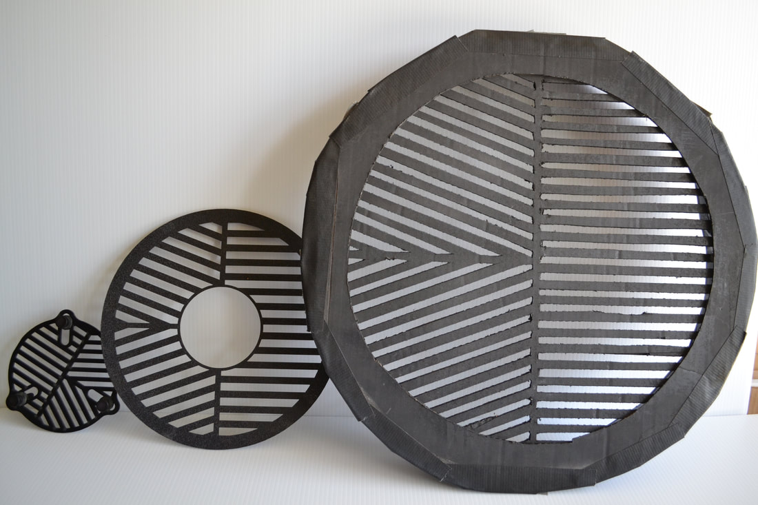 • Commercial Bahtinov masks for a 127mm refractor and 9.25" SCT. Homemade cardboard mask for a 14" SCT The Bahtinov mask must be sized for the particular OTA. Some versions like the smaller one shown in the image above are adjustable and can fit several different telescope sizes. Masks for SCTs typically have a hole in the center to accommodate the secondary mirror or a Hyperstar adapter. The ones from Farpoint are fairly inexpensive, work well and are the ones I typically use. Some telescope manufacturers like Williams optics now incorporate the Bahtinov mask into the dew cover for their 81mm doublets. One can even make their own masks like the cardboard one I made for my 14" SCT shown above.  Telrad Unity Finder Telrad Unity Finder Finder Scope Once focused it is time to align the telescope. Most, but not all, telescopes come with a finderscope, either an 8 or 9 x 50. That is a magnification of 8 or 9 and a 50mm lens. I find that it is much easier to use a Unity Finder than the typical 8 or 9 x 50 finder scope. If using a telescope like my 9.25" SCT or larger I use a Telrad Unity Finder which uses a red LED to project 3 concentric circles onto a clear plastic screen. The circles cover 1/2, 2 and 4 degree FOVs. The LED can be dimmed and is powered by 2 AA batteries. By sighting through the circles I can see the alignment stars through the clear screen with the red circles superimposed as I adjust the mount to bring the intended star into the FOV of the telescope. For me, this is faster and usually less confusing compared to looking through an 8X or 9X finder with a greatly magnified image and many more stars. After all, the alignment stars are most always naked eye stars and the final alignment of the mount will use the camera view through the telescope and not the finder. An optional dew shield and optional dew heater are available to prevent dew formation on the clear screen. Like any finder, the Telrad must first be aligned to the telescope which is best done at night with a bright star. The moon can be used for rough alignment followed by a star for more precise alignment. The Telrad attaches to a base with two thumb screws for easy removal for travel. The base attaches to the telescope using supplied double sided tape. Another advantage of the Telrad is that it is less expensive than a typical optical finder scope. Rigel makes a similar unity finder with concentric circles but with a smaller base and a higher stance off the OTA compared to the Telrad. It is powered with a lithium battery and has an adjustable led intensity and a pulse mode as well. I use this one on my 80mm refractor as the Telrad is to large for that size telescope. Other options are the Red Dot finders which are also unity finders which project a red LED as a dot on a clear plastic window. Simply look through the window and adjust the mount until the red dot is on the star to align the mount. I use these smaller finders on my 6" SCT. The one thing to keep in mind with all of these unity finders is that if you view through the finder from an angle instead of from directly behind the star will appear to move of the red dot which will lead to an offset in the alignment. This is not difficult to manage but if you want the state of the art in unity finders, Tele Vue makes a version where the star remains fixed even when viewed from 2 feet off axis. The catch is that instead of costing under $50 the Tele Vue Star Beam costs $347. 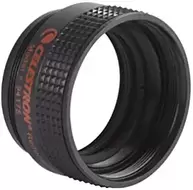 Celestron f/6.3 focal reducer/corrector Celestron f/6.3 focal reducer/corrector Focal Reducer One of the most common and useful accessories for EAA is the focal reducer. Unless your telescope is already at f/6 or faster like many Newtonians, you will find that a focal reducer is an essential tool to make EAA more enjoyable. A focal reducer does two important things. First, it increases the field of view (FOV) of the optical system. A large FOV makes it much easier to find very dim objects, especially with a small sensor and a rough GoTo alignment. In addition, a large FOV is necessary to fit large DSOs like M33 fully into the camera frame. Likewise, a focal reducer can be helpful for fitting multiple smaller DSOs into the frame. While full screen views of the galaxies M81 and M82 can be wonderful in their own right, adding a focal reducer to the optical path to bring both galaxies into a single FOV which gives an entirely different perspective on the these two interesting but very different galaxies. And there really is no other way to appreciate galaxy clusters like the Virgo cluster without a focal reducer to capture them with the necessary large FOV. As we discussed in the third article in this series, "Choosing a Telescope for EAA" a focal reducer has the effect of reducing the native focal length and focal ratio of a telescope. Since the FOV is inversely proportional to the focal length, an f/5 focal reducer will decrease the focal length of the telescope by a factor of two Focal Length with f/5 reducer = Native Focal Length x 0.5 which conversely increases the FOV by a factor of two. The second important function of a focal reducer is to increase the speed of the telescope so that images can be captured and viewed with much shorter exposures. For instance, the Celestron f/6.3 focal reducer combined with an f/10 SCT will reduce the focal ratio to f/6.3. Since the speed of a telescope is proportional to the inverse of the focal ratio squared, the X6.3 focal reducer speeds up the telescope by 2.5X Telescope Speed = (10/6.3)^2 = 2.52 So the exposure for a given object can be reduced by a factor of 2.5 to provide an equivalent brightness view compared to the one at f/10. Of course, the trade-off is the reduction in the magnification resulting in an image which appears equivalently smaller. In other words, the same photons are captured but concentrated into a smaller number of pixels in the camera which both reduces the exposure and reduces the size of the object. This is demonstrated in the images below using the free analysis software CCDCalc to show the FOV for an ASI533 camera and an 11" SCT at its native f/10 and using a Hyperstar lens to reduce the focal ratio all the way down to f/2. As illustrated by the white rectangles overlaying the images of M81/M82 below, the FOV is sufficient at f/10 to capture only M81 while at f/2 both galaxies fit nicely in the FOV. Focal reducers can be found with a range of focal reduction values from ~0.8X to 0.5X. Many focal reducers combine focal reduction with field flattening to bring the entire field into focus at the same point resulting in round stars all the way to the edge of the FOV. The popular Celestron f/6.3 focal reducer/corrector has a reduction factor of 0.63X and is designed to work with non-Edge SCTs, as is the very similar Meade f/6.3. These provide focal reduction, correct for coma and also flatten the field of view. Celestron has a separate 0.7X focal reducer for its Edge series of SCTs. Focal reducers for refractors generally come in 0.8X and 0.75X versions and may or may not also provide a flat field. In general, focal reducers are available from telescope makers like Televue, Explore Scientific, Sky Watcher, Orion, etc. and are optimized for their specific telescopes. Examples are the Celestron f/6.3 for their non-Edge SCTS, the TeleVue 0.8X reducer/flattener for their 102mm refractor, The Sky-Watcher 0.77X reducer/field flattener for their Esprit 120mm refractor, and others for most every brand of telescope. In addition to these telescope specific reducers, there are a number of generic focal reducers which can be used for most any telescope from the likes of Optec, Starizona, Baader Planetarium, etc. For modest budgets there are many different 0.5X focal reducers in the 1.25" and 2" formats from, GSO, Antares, Svbony and others. These use an inexpensive single lens commonly found in binoculars and work very well for cameras with small sensors, less than 10mm. On larger cameras one may notice distortions and aberrations at the edge of the FOV with these inexpensive reducers. For focal reducers to achieve the stated focal reduction without causing aberrations or distortions in the image they must be positioned at the manufacturer's designed spacing from the camera's image plane. This distance varies by design and is usually measured from the base of the mounting threads on the back of the focal reducer to the camera sensor. In some cases it is measured from the center of the rear lens of the focal reducer to the camera sensor. For example, the ideal spacing is 105mm for the Celestron f/6.3, 146mm for the Celestron Edge f/7 for the 9.25", 11" and 14" models but only 133.35mm for the 8" Edge. Focal reducers for refractors are most commonly designed for a spacing of 55mm. Typically, to get the correct reduction factor and avoid optical aberrations, the spacing must be correct within 1 to 2mm so the proper set of spacers will be required. It is important to note that a focal reducer will move the image plane closer to the focuser so it is critical to make certain that the focuser has sufficient in focus travel to accommodate this. Also, if the focal reducer is spaced further from the imaging plane the reduction factor increases so the FOV gets even larger. However, in most cases this will cause optical aberrations and vignetting which may or may not offend the user. On the other hand, if the focal reducer is spaced closer to the imaging plane the reduction factor the reduction factor decreases which does not cause vignetting issues. For those willing to accept some amount of vignetting and image distortion near the field edge, two focal reducers can be combined to achieve an even greater reduction and faster imaging platform. An excellent overview of focal reducers is available on the Agena Astro web site here. Dew Control Unless you only observe from a desert, you will eventually encounter dew buildup on your optics. The first line of defense is a dew shield which attaches to the front of the telescope and keeps the corrector or objective from forming dew in moderate dew conditions. Fortunately refractors come with a dew shield as part of their design. Many retract for storage and extend when in use. Newtonians are less susceptible to dew formation on the primary mirror since it sits well back in the tube which acts like an extra long dew shield. The main concern for Newtonians is dew on the secondary which is why many are designed with the secondary set back inside the tube allowing it to act as a fixed dew shield like on many refractors. If you have an SCT you will need a dew shield. These are available from many manufacturers and come either as either a flexible plastic or rigid aluminum cylinder. These are usually felt lined to prevent stray light from reflecting of the sides and into the telescope. As such, these dew shields serve the secondary purpose of deflecting any off axis light from interfering with the image. The flexible version is held in cylindrical form with velcro attached to one side which means it can be flattened for storage or transport. Both the flexible and rigid type also come in versions with notches to fit around dovetails and with additional notches for camera cables when using a Hyperstar lens. The aluminum versions add more weight at the front end of the SCT which will have to be balanced by moving the SCT back in the mount saddle. When the dew shield is not sufficient to prevent condensation of water on the optical surfaces active measures are required and this is typically achieved with a dew strap and dew heater. Dew straps come in sizes to fit most every telescope. Simply wrap the dew strap around the outside of the telescope near the optical element at the front of the telescope exposed to dew such as the objective of a refractor or the corrector plate of an SCT and run the included wires down to a dew controller for power. The dew strap has a series of resistors which produce a mild heat at the surface of the telescope to keep the temperature near the glass surface above the dew point. A good practice is to add a layer of reflectix to top of the dew strap to minimize the heat loss to the air which will help to minimize the power required for the dew heater. Reflectix can be found at your local Home Depot or Lowes hardware stores. There are many dew controller options. These all come with multiple channels to power two to four separate dew straps. The outputs can be adjusted from 0 to 100%. I use the Astrozap which has four channels, controlled in pairs. The Thousand Oaks model also has four channels but each channel can be independently controlled. I have never had the need for more than two channels so the Astrozap has worked well for me. A nice feature of the Thousand Oaks controller is the addition of a 12V power outlet to provide dc power to an additional accessory. I recently purchased a Pegasus Astro Pocket Powerbox Advanced as a power and USB hub for my setup and it has 2 independently controlled dew control channels which can be adjusted in the included software. The nice feature of this controller is that it comes with a temperature and humidity sensor which can be used to automatically control the dew controller settings. Another option in dew control is a dew shield with built in dew heater strap. I have used these for my Celestron 14" and Celestron 9.25" SCTs but prefer the stand alone dew strap and separate dew shield. Astrozap dew strap and dual channel dew controller 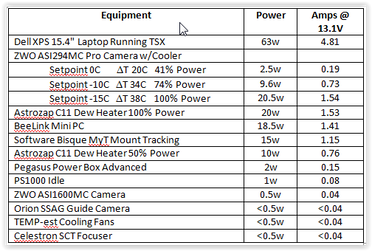 Power I have posted a comprehensive review of power options which addresses power needs, distribution of the power from the source to the equipment and the many different power source option pros and cons. It can be found here so I will not repeat all of that in this blog article. If possible it is best to measure the power needed by using a watt meter or a digital multimeter, DMM. A watt meter is easiest as it measures both current and voltage at the same time. A little more effort is required to measure current and voltage with a DMM as these need to be measured one at a time or at the same time with two DMMs. On the other hand, a reasonable estimate of power needs can be made from the data in the table shown below. These are actual measurements of the power used by each device in my own setup. An EAA setup does not need a guider and does not need a cooled camera although both can be used. Most cameras will use less than 0.5W of power and a typical tracking mount can be expected to consume ~10W. The biggest power hogs are laptops and dew heaters. A relatively simple EAA setup with camera, mount, power/USB hub, and dew heater should need between 15W and 30W not counting the laptop. Add ~10W if you use a cooled camera as you do not need to run the camera cooler at full power for EAA. There are so many power supply options that it can be confusing for many. The cheapest upfront option is an AGM battery. These are available in capacities of 50Ah for ~$100 and 100Ah for ~$200. Keep in mind that AGMs should not be discharged more than 50% to 80% of their capacity depending upon the manufacturer's specifications. Exceeding this will cause permanent damage and a shortened life. Many prefer to use only 50% of the capacity to extend the life of an AGM battery. For those with the long term view, an AGM is not the cheapest option given its depth of discharge (DOD) constraint. LiFePO4 batteries are much more cost effective when viewed over the long term, although their upfront cost will be much higher. LiFePO4 are used extensively as replacements for AGM batteries in the RV and boating industries. These batteries have an internal battery management system (BMS) which allows for a 100% DOD without damaging the battery. The trick is the BMS holds some power in reserve when it shuts down so the lithium cells have not actually be fully depleted. For those who need a large capacity LiFePO4, something like the Battleborn battery which is manufactured in Sparks Nevada is a good option. For lesser power needs, the Talentcell line of small capacity batteries tend to be more cost effective than the astronomy specific Celestron or Meade batteries. For those who need more than just a dc power source, the all-in-one solar generators from companies like Jackery and Maxoak Bluetti are solar re-charge ready, have a built in pure sine wave inverter which can be used to power any AC devices like a laptop, have several different USB type charging ports, meters, a display and more. These use Lithium Nickel Manganese Cobalt Oxide, commonly abbreviated as NMC. NMC batteries have a higher energy density per unit weight than LiFePO4 and are used in electric cars, ebikes, power tools, etc. The all-in-ones come with a range of capacities from 167Wh to over 2400Wh. and are the most expensive options out there. But, they are multi-purpose and make good emergency power backups at home since they can be safely operated inside the house unlike a gas generator. So, these are the accessories that I consider essential for EAA. One can certainly start without them, but I believe these will be the most helpful accessories one could buy and the sooner you have them the better your EAA sessions will be. There are certainly many other accessories which people find helpful but these can be added in time. Amazon and OPT links are Associate/Affiliate links from which I can earn commissions at not cost to you.  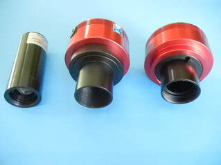 Lodestar X2C, ASI1600MC, ASI224MC Lodestar X2C, ASI1600MC, ASI224MC You might ask, "What is the difference between a camera for EAA and one for astrophotography?". The answer is, nothing really. There is no hard and fast line between the two activities. Any camera that will work for astrophotography will work for EAA and vice-a-versa including DSLRs. Now, there are cameras that are more commonly used for EAA and these are the cameras with CMOS sensors selling for a few hundred dollars to no more than ~$1500. Based upon posts on multiple forums, I would estimate that the most common EAA cameras fall into the price range of $250 to $1300. Again, there is no hard and fast rule here. But you will find that the cameras costing more than ~$1500 are generally used by astrophotographers and not those doing EAA. Astrophotographers have traditionally used cameras with CCD sensors because of their higher sensitivity compared to CMOS sensors. But that is changing as the sensitivity of CMOS sensors is approaching that of CCD sensors while the CMOS sensors have the advantage of much lower read noise. Lower read noise makes live stacking of short exposures extremely practical for EAA. In addition, the two major suppliers of CCDs are Sony and On Semiconductor. In 2015 Sony announced that it would stop development of new CCDs by 2017 and On Semiconductor announced it would stop production of all CCDs in 2020. So as supplies of CCDs on hand dwindle, new astronomy cameras will eventually only use CMOS sensors. Therefore, in this blog we will concentrate on those with CMOS sensors costing no more than ~$1500 and only discuss a few using CCDs. That will leave out many CCD cameras from companies like SBIG, QSI, FLI, Apogee, QHY, Starlight Xpress, and Atik which are more often used by astrophotographers. Another important point that needs to be made is the distinction between cameras for Deep Sky Object (DSO) viewing and cameras for planetary viewing. Once again there is no hard and fast line between the two, but typically cameras for planetary work have smaller sensors, fewer pixels and higher frame rates. This is because the planets are small bright objects and lucky imaging is employed to capture thousands of sub-second frames from which a few hundred of the best images are used to create a final image. In contrast, DSOs are much larger and fainter and exposures are several seconds to tens of seconds in length. Having said this, both types of cameras can produce pleasing images of both types of objects. Cost For most of us, the cost of a camera for EAA is the primary driver of what we ultimately buy. Fortunately, it is not necessary to spend a lot of money for a camera for EAA. An entry level camera like the 1.2 Mega Pixel (MP) Rising Tech IMX224 camera with the 6.1mm diagonal Sony IMX224 color sensor is available for $165. If you already have a telescope on a motorized mount the cost of entry is very minimal. While the IMX224 sensor is small, it is quite capable and provides a cost effective option for the EAA beginner. In fact, when first introduced around 2015, the ASI224MC using this sensor and costing $300 was widely popular as one of the earliest CMOS cameras to be employed by the EAA community. As larger CMOS sensors became available, cameras with increasing pixel count and sensor size have been widely adopted for EAA. It is now possible to find CMOS based astronomy cameras prices from the $165 camera mentioned above to many thousands of dollars. The most commonly used EAA cameras today have color sensors with pixel counts of ~9MP to ~20MP, and sensor diagonals of ~15mm to ~23mm. Obviously as the sensor size increases, the cost goes up as well. Other drivers of cost include a Peltier cooler to minimize thermal noise , an internal memory buffer to prevent lost frames during image download and a USB hub for connection to a focuser and guide camera. We will review a comprehensive list of available cameras and cost once we discuss the key camera attributes we need to understand before choosing which camera is best for our needs. Color or Mono (B&W) Perhaps the most important consideration when choosing a camera for EAA is whether to choose a color or monochrome camera. Many cameras are available with either color or mono (black and white) sensors. Color sensors are just mono sensors with a red, green and blue filter matrix on top of the individual pixels. This matrix is called a Bayer matrix after the Kodak scientist who invited it in 1976 to turn a mono camera into a color camera. Because the human eye is most sensitive to green light, the Bayer matrix is typically arranged as a 2 x 2 matrix of pixels with 2 green and 1 each red and blue filters. These days, the filters also act as micro lenses to focus off axis photons onto the pixel thereby maximizing the light collection sensitivity of the sensor. Sometimes cyan, magenta and yellow filters are used instead of red, green and blue but the result is the same. To realize the full real time viewing experience only a color camera can show the rich colors present in nebulae, star forming clusters in distant galaxies and the different colors of stars at various stages of their lives. Being able to view objects in color is one of the major advantages of EAA compared to viewing with an eyepiece (EP). Because of the filter matrix associated with a color camera, some sensitivity is lost compared to a mono camera as a trade off for the simplicity of a one shot color camera (OSC). While there is nothing preventing the use of a mono camera for EAA, they are more often used for astrophotography combined with external filters to capture images at each color which are combined later to form a full color image. Some EAA'rs use a mono camera to view DSOs in black and white in real time to take advantage of the added sensitivity of a mono camera, or even use a mono camera with one of the possible narrow band filters available (hydrogen, oxygen, sulfur) to view specific detail in deep sky objects. This may be a good approach if you ultimately want to pursue astrophotography as well. We will see below that cameras with the mono version of a particular sensor cost significantly more than the color version which is another reason for the greater popularity of a OSC camera for EAA. Chip Size The size of the sensor chip will determine many important attributes of the camera. Most important, the larger the size of the chip, the bigger the field of view (FOV). In the Blog "Choosing a Telescope for EAA" we made the point that the FOV for an optical system consisting of a telescope and a camera is given by the equation: FOV ~ 57.3 L / F where L is the length of one side or diagonal of the sensor chip in mm, F is the telescope focal length in mm and FOV is in degrees. So the larger the sensor chip the larger the FOV. For instance, let's take the case of an 8" SCT with a Celestron f/6.3 focal reducer to achieve a focal length of 1260 mm (2000 mm x 0.63). Assume we are using one of the cameras like the Rising Tech 224 or the ASI224MC, with the 6.46mm diagonal Sony IMX224 chip. The FOV will be 0.29 degrees along the diagonal, slightly larger along the long axis and slightly smaller along the shorter axis of the chip. Now, if instead we use a camera with the Sony IMX294 chip with a diagonal of 23.2 mm the FOV will be 1.05 degrees along the diagonal which is 3.6 times larger. The larger chip size has several advantages. First, it allows us to capture much larger DSOs in a single image frame. An excellent tool for calculating FOV and image scale for different optical configurations is Ron Wodaski's CCDCalc. The side by side images below were generated by CCDCalc using a telescope with a focal length of 1260mm (our 8" SCT with f/6.3 focal reducer or any other telescope combination to achieve the same focal length) and the IMX224 and IMX294 camera dimensions. Clearly, something like the Triffid Nebula is too large to fit into a single frame with the much smaller chip of the IMX224, but fits nicely into the chip of the IMX294. In addition to enabling larger DSOs to fit inside a single frame, the larger FOV can make it much easier to align the telescope and to find objects because of the larger FOV. In effect, the sensor diagonal acts like the focal length of an EP in determining the FOV. So, the IMX224 with a diagonal of ~6.5mm gives a similar FOV as a 6 to 7 mm focal length EP, while the IMX294 gives a similar FOV as a 23 mm focal length EP. On the other hand, the smaller sensor, like the smaller focal length EP, provides higher magnification of an object compared to the larger sensor. Compare the image frames for M61 below between the IMX224 and IMX294 sensors. Obviously, the image will appear larger on the computer screen with the IMX224 sensor and will fill the frame while the image appears much smaller with the IMX294 sensor. Now there is a trick here. The IMX224 has only 1.2MP while the IMX294 with 11.3MP has nearly 10X the number of pixel. The image from the IMX294 can be zoomed in or viewed on a much larger screen like a 60" TV without producing a blocky or pixelated image whereas the IMX224 image doesn't have enough pixels to do that. The IMX224 image will support a 720p video display format which is just below full HD or 1080p, while the IMX294 has more resolution than a 4k video display. Having said that, the IMX224 resolution is more than 2X that of the analog video cameras with 0.4MP which were the only options for EAA up until ~ 2015. Another thing to be aware of as the sensor size increases, vignetting of the image will become more obvious. As the light travels through the optical path any narrowing of that path due to baffling inside the tube, the diameter of the opening at the back end of the telescope, the focuser, any adapters, focal reducers, filters, etc. can block some of that light toward the outer radius of the FOV. This will show up as a halo toward the outer edge of the image. This is typically not a problem in the very small sensors less than 10mm in diagonal. Focal reducers will make vignetting worse as they push the light cone further back from the exit of the telescope. Vignetting may or may not be an issue for the individual viewer depending upon how severe. This is why APS-C (28mm) and full frame cameras (43mm) can be challenging. However, vignetting can be corrected with flat frames applied to the image on the fly with live stacking software. It should also be noted that as the sensor size increases, so does the number of pixels which means that file sizes get larger fast. This directly impacts the the amount of computer storage necessary if one wants to save images. It also can impact the ability to stack images live in software if the computer used doesn't have sufficient CPU capability.  Read Noise vs Gain for the QHY163c camera, from QHY website Read Noise vs Gain for the QHY163c camera, from QHY website Read Noise The biggest driver of the move from CCD cameras to CMOS cameras after cost has been the fact that CMOS cameras have amazingly low read noise. What is read noise? It is the random noise due to the uncertainty in counting the number of electrons created in each pixel by the photons striking that pixel. Read noise is independent of the signal, or amount of photons collected, so it is independent of the exposure. This noise is introduced into the image data when the captured image frame is downloaded from the sensor to the output device, display and computer hard drive. Read noise for CCD cameras is typically greater than 5electrons (5e). The Atik Infinity camera with the Sony ICX825 CCD has a read noise of 6e while the Starlight Xpress UltraStar using the Sony ICX825 CCD has a much better read noise of 3.5e. CCD cameras used for astrophotography like the SBIG STF-8300 have as much as 9.3e of read noise. In contrast, CMOS cameras can have a read noise less than 2e depending upon the gain setting used. At this level, the read noise is less than the other sources of noise which impact the image and can effectively be ignored for EAA. The read noise is a strong function of gain used as shown in the plot from QHY below. A lower read noise means that there is no penalty for taking many short exposures and stacking them live rather than taking a single long exposure. In fact, commensurate with the introduction of these low read noise CMOS cameras, live stacking software like SharpCap became widely available. Whereas in the bygone days of analog cameras with CCD sensors we used exposures of 30 seconds to several minutes to bring out detail in our images, EAA has moved more toward stacking many very short exposures, 5 and 10sec, to achieve the same total exposure time now that live stacking software is readily available. The ability to use many short exposures has had multiple effects on EAA. First, instead of waiting a minute to see something on our display, we begin to see the faint evidence of a DSO in very short order. This gets better in real time right before our eyes with more detail and less noise with each additional frame added to the stack. Second, the use of short frames means that a less than perfect polar alignment of our equatorial (EQ) mount does not cause objectionable star trailing since the exposure is not long enough to show the effect of an imperfect alignment. Third, with very short exposures we can now use Alt-Azimuth mounts for EAA which are simply out of the question for traditional astrophotograpy. Alt-Az mounts have the advantages of being much easier to set up since a polar alignment is not needed nor is one possible. Also, Alt-Az mounts tend to be less expensive than EQ mounts. Fourth, shorter exposures can also help to avoid saturation of bright stars in the FOV, thus improving the dynamic range of the viewed image. So, low read noise can be a big plus for EAA enabling short exposure live stacking, the use of less expensive mounts, and a simpler setup routine. Fortunately, most CMOS cameras have exceptionally low read noise and one can concentrate on other features in deciding which camera is best suited to their EAA needs. 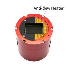 Cut-away view of anti-dew heater Cut-away view of anti-dew heater Cooling Yet another choice one must make in selecting a camera is whether to purchase a cooled or uncooled camera. Many models are available with Peltier or Thermo Electric (TEC) cooling of the camera sensor to minimize thermal noise. Thermal noise is the result of heat buildup inside the camera from the camera electronics and from the background air temperature. Thermal nose results in a dark current within the camera sensor which shows up as random noise in the background of an image frame. Thermal noise is fairly predictable at a given temperature and can be controlled with a well regulated TEC. A TEC typically allow for temperatures to be maintained ~ -35 to -40 degC below ambient. Cooling is more important for long exposures as the heat built up in the camera during these long exposures is greater than in short exposures. Therefore, if the strategy is to stack many very short exposures, say 10sec or shorter, the advantage of TEC cooling may not be worth the added cost and complexity. Also, the background noise from the dark current can also be very effectively removed by using dark frame subtraction. A set of dark frames, typically 16, can be collected and averaged at the exposure planned for live viewing. The dark frame average is used as a master dark frame which can then be subtracted on the fly with live stacking software like SharpCap to remove the dark noise from each frame. For this to be effective, the dark frames must be collected at the same exposure time, gain and temperature as the frames during live viewing. Also, because ambient temperatures can drop significantly during the night, new dark frames may need to be taken and a new master dark frame used throughout the night. On the other hand, with TEC cooling, a library of dark frames can be made ahead of time at different exposure times and temperature offsets from ambient to be used as needed throughout the night. This library can be made during the day or during a cloudy night so that no time is wasted on nights with good visibility. Several things need to be considered when using a camera with a TEC. First, the lower temperature at the sensor can result in dew buildup on the sensor and on the camera's glass window. Many cooled cameras come with a sealed chamber to minimize water vapor causing dew build up inside the chamber. This still leaves the outside glass window of the chamber exposed to dew buildup which is why many cooled cameras now come with a dew heater strip surrounding the chamber window. Second, while the camera itself requires very little power, typically less than 2.5W which can be supplied via the USB connection to the camera, cooling requires an additional 12V power supply capable of supplying ~20 - 35W and an additional cable to the camera. Consideration for extra battery capacity when visiting a remote dark site is also necessary with a cooled camera. 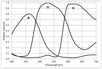 Quantum Efficiency for ZWO ASI294MC from ZWO website Quantum Efficiency for ZWO ASI294MC from ZWO website QE, Full Well Depth, Bit Depth, Frame Rate With so many different specifications for the sensors inside astronomy cameras, there is not single ideal camera. Most likely, once you determine the price range you plan to spend, whether to go with color or mono, cooled or uncooled and the chip size that will work best for your application, the remaining specs will already be determined. Nonetheless, it is worthwhile to go over those additional specifications as they will impact the performance of the camera. Quantum efficiency (QE) is a measure of how well the pixels in the sensor convert an incoming photon into electrons. The silicon which makes up the sensor is responsive to light over a range of wavelengths centered in the visible but extending into the near infrared and ultraviolet, typically from ~300nm to 1,000nm. The QE varies with wavelength and is usually expressed in a graph with separate curves for red, green and blue light. Quantum efficiencies can vary quite a bit with values ranging from 50% to 84% for typical EAA cameras. The lower the QE the longer the exposure needed to collect the same amount of photons compared to a higher QE.  A 16bit sensor has a finer graduation grey scale compared to 14bit. Source ZWO A 16bit sensor has a finer graduation grey scale compared to 14bit. Source ZWO Another important attribute of the sensor inside a camera is called the full well capacity. This is a measure of the maximum number of photons that a pixel can collect before it is full of electrons and cannot detect any additional photons. The full well capacity is proportional to the size of the pixels with larger pixels capable of capturing more photons before they become full. Full well capacities can vary significantly from camera to camera with a range of about 15K electrons for the IMX183 sensor with a 2.4 micron pixel size to 64K electrons for the IMX294 sensor with a 4.63 micron pixel size. Full well capacity will determine the range between the brightest object and the dimmest object. If the full well capacity is small, bright stars will saturate unless the exposure is shortened which will reduce the intensity of the dimmer objects in the FOV. All other things considered, a higher full well capacity is preferred. It should be noted that the stated full well capacity is measured with zero gain. Gain is equivalent to the ISO setting on a DSLR camera which multiplies the number of electrons captured at each pixel thereby increasing the camera's sensitivity by allowing resolution of smaller differences in the number of electrons captured. Gain values can be anywhere from 0 to ~450 depending upon how the camera manufacturer sets it up. The trade-off with higher gain is reduced dynamic range. Dynamic range is the ratio of the largest signal (brightest object) to the smallest signal (dimmest object or background sky). A large dynamic range is desired to show the full range of objects without washing out the brightest ones in the image. For instance, a large dynamic range is needed to capture the dark dust lanes without blowing out the core of a galaxy. As gain is increased the full well capacity of the camera is reduced because the multiplication factor uses up more the the well capacity. This, in turn, causes the dynamic range to decrease. So gain helps with sensitivity but hurts with dynamic range. Yet another specification that you will find with each camera is bit depth. Typical cameras used for EAA have bit depths of 12 or 14 but some of the newest higher prices cameras are 16 bit. What is bit depth? After the camera captures an image frame an analog to digital converter (ADC) converts the analog voltage associated with the number of electrons in a pixel into an integer or digital value. With a 12 bit device, 2^12 or 4096 discrete values are possible for each pixel. At 12 bits, the camera uses a bit value of 0 for no voltage detected and 4096 for the maximum voltage detected. A 14 bit device has 4 times as many possible values so it also uses 0 for no voltage but can now use 16,384 bits for the maximum voltage detected providing a finer scale with which to better differentiate details within an image. A bit depth of 14 is most common among the current batch of CMOS cameras, but 16 bits is starting to show up in the latest high end CMOS cameras. A 16 bit device has 65,536 possible values. The more bits possible, the finer the resolution in the photon levels detected. All other things considered, a camera with a higher bit depth is desirable. Above is a comparison from ZWO showing the increased grey scale resolution with more bits Cameras will also have a maximum frame rate specification which indicates how many full frame images can be downloaded from the camera per second. The download rate may be limited by external cabling, with USB3 supporting higher data rates than USB2. Frame rates are not super important for EAA since exposures are a few seconds or longer. Frame rates of 10 to 23 frames per second (FPS) are typical for cameras commonly used for DSOs. This is in contrast to planetary cameras with frame rates of 20 FPS to 170 FPS. Which is not to say that a camera used for DSOs cannot also be used for planetary imaging; just that it is not optimized in terms of pixel size and frame rate for planetary work. Another point to note, with binning the frame rate will increase since there are less individual pixels of data to transfer. 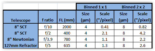 USB Hubs, Internal Memory, Binning, etc. There are several other features to consider when choosing a camera which will be discussed here. Most CMOS cameras today allow binning of the sensor pixels which simply merges the signal from adjacent pixels into one larger pixel. Typically binning is available in 2x2, 3x3 and even up to 4x4. Binning 2 x 2 means that four adjacent pixels are combined into one, which effectively increases the pixel size by a factor of 4, improves the sensitivity by a factor of 4, but reduces the resolution by the a factor of 2. Binning 3 x 3 combines a 3 pixel square of 9 pixels into one and 4 x 4 binning combines a 4 pixel square of 16 into one very large pixel. Because of the increased sensitivity, binning is helpful when searching for objects, doing an alignment and framing targets as it shortens the time needed to get a recognizable image. How does binning with a OSC camera keep the color since the adjacent pixels have different (R, G, B) color filters? The answer is that the binning is done in software which allows the camera to deBayer the image before binning so as to preserve the color information. Now that we are discussing binning, we need to also visit the concept of image scale. Recall from the Blog " Choosing a Telescope for EAA" that image scale is determined by the ratio of the sensor pixel size to the telescope focal length. Image Scale (arcsec/pixel) = 205 x Pixel Size (microns) / Focal Length (mm) Now, it is widely accepted that typical seeing limits observable detail to ~ 2 arcsec per pixel. On nights of better seeing an image scale less than 2 arcseconds per pixel is possible. Consider an 8" SCT at f/10 with a focal length of 2000 mm. Let's use 4 microns as an approximate size of a pixel in a typical EAA camera. This gives an image scale of 0.41 arcsec/pixel which is much smaller than the typical seeing which means that we are oversampling relative to the sky conditions. Now, what if we use a Hyperstar lens to achieve a focal ratio of f/2 so that the telescope focal length is now 400mm. In this case we are operating at ~2.1 arcsec/pixel which is perfect for typical seeing conditions. Take another example of an 8" Newtonian at f/3.9, or 780mm which gives an image scale of ~1.1arcsec/pixel. And last, consider a 127mm refractor at f/5 with a focal length of 635mm which leads to an image scale of ~1.3 arcsec/pixel. The point is that with the small size of CMOS sensors, with most telescope setups we will be oversampling relative to a 2arcsec/pixel seeing limit. There is no harm in this, but it does say that we can bin 2x2 and get the advantage of 4X the sensitivity without loosing significant resolution in all but the best seeing conditions. With 2x2 binning of a 4 micron pixel the pixel size becomes 8 microns and the image scale increases accordingly as shown in the table below. Because the image scale with typical CMOS pixel sizes is much smaller than 2arcsec/pixel, binning will not reduce the resolution unless the seeing conditions are sub 2arcsec/pixel or even sub 1arcsec/pixel. Another concept we should discuss is amp-glow. In the days when we used analog cameras with CCD sensor all cameras had to deal with amp-glow. Amp-glow appears as a bright region at an edge or corner of the image which is caused by IR radiation from the read out amplifier. These IR photons are picked up by the nearby pixels and show up as a background glow, hence the name amp-glow. Now, CMOS sensors have completely different circuitry but can still suffer the effects of glow from the other on board circuitry and this varies from camera to camera in intensity, number and shapes of glowing regions. The pictures below show several different types of amp-glow possible with different sensors. Amp-glow can be handled with dark frame subtraction which, for EAA, means live stacking software must be used. Some cameras advertise amp-glow control which can virtually eliminate the effect without dark frame subtraction. An internal memory buffer is used to increase the readout speed thereby reducing the time the readout circuits are active. Several camera makers also have "Anti Amp-Glow" hardware and software which reduces the power in the CMOS circuitry thereby minimizing amp-glow but no real details are given about how they do this. Minimum and maximum exposures vary by camera but typically have a minimum of tens of micro seconds which is sufficient for bright planetary objects and maximums of 30 to 60 minutes which is much more than is needed for EAA. The Atik Infinity has the shortest maximum exposure of 120 seconds but because it uses the very sensitive Sony ICX825 CCD this is more than sufficient for most EAA applications but does limit the total time for live stacking to 2 minutes. Most dedicated astronomy cameras these days come in a cylindrical shaped body which are designed to have a small footprint. This is important when using the Hyperstar adapter on an SCT as it minimizes the amount of incoming light blocked by the camera. The bodies are typically ~3" or smaller in diameter. The ATIK Infinity is an exception as it has a rectangular body 70 x 113mm in dimensions. On the other hand, cooled camera bodies are 4" to 5" long which means that they will run into the base of some Alt-Az mounts like the Celestron Nexstar mounts. 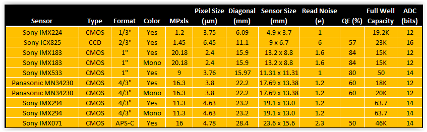 Camera Options for EAA Like mounts and telescopes, there are far too many cameras available for EAA to cover them all. We will concentrate on CMOS cameras with two exceptions for popular CCD cameras. Also, it is important to note that the manufacturers of the cameras we will discuss use the same sensors from Sony and Panasonic so one can find very similar cameras from ZWO, QHY, Mallincam, Rising Tech, Altair Astro, etc. Below is a table of the key characteristics of the most commonly used sensors in EAA cameras. The table is arranged from smallest to largest diagonal. Many of these sensors come in both a color and mono version, although color is much more commonly used for EAA to get the full benefit of real time viewing. The advantage of the mono sensor is its higher sensitivity, especially when used with narrow band filters to cut through local light pollution. The smallest sensor is the IMX224 which was discussed above and can be found in the least expensive cameras. Most sensors have diagonals in the range of 16mm to 22mm which can result in obvious vignetting especially if significant focal reduction is used. Vignetting can be addressed with flat fields when using live stacking software or minimized with a telescope which has a large fully illuminated image circle. Vignetting is especially problematic when an APS-C format sensor like the IMX071 is used or a Full-Frame sensor like the IMX455. We will not discuss the Full-Frame format sensors and cameras here as they are much more suited to astrophotography even though certainly can be used for EAA. The values of the Read Noise given in the table are the minimums as Read Noise varies with the Gain used. Quantum Efficiency (QE) is not available for all sensors for some reason. Cameras are available for most of the sensors shown with TEC cooling. Also, all but a very few of the cameras come with a USB3.0 connection to the camera which provides faster download speeds compared to USB2.0. Camera bodies are all cyclindrical with the exception of the Atik Infinity. TEC cooling requires a much larger camera body length which will not clear the base of an Alt-Az mount when pointing near the zenith unless it is one of the side mount Alt-Az telescopes. 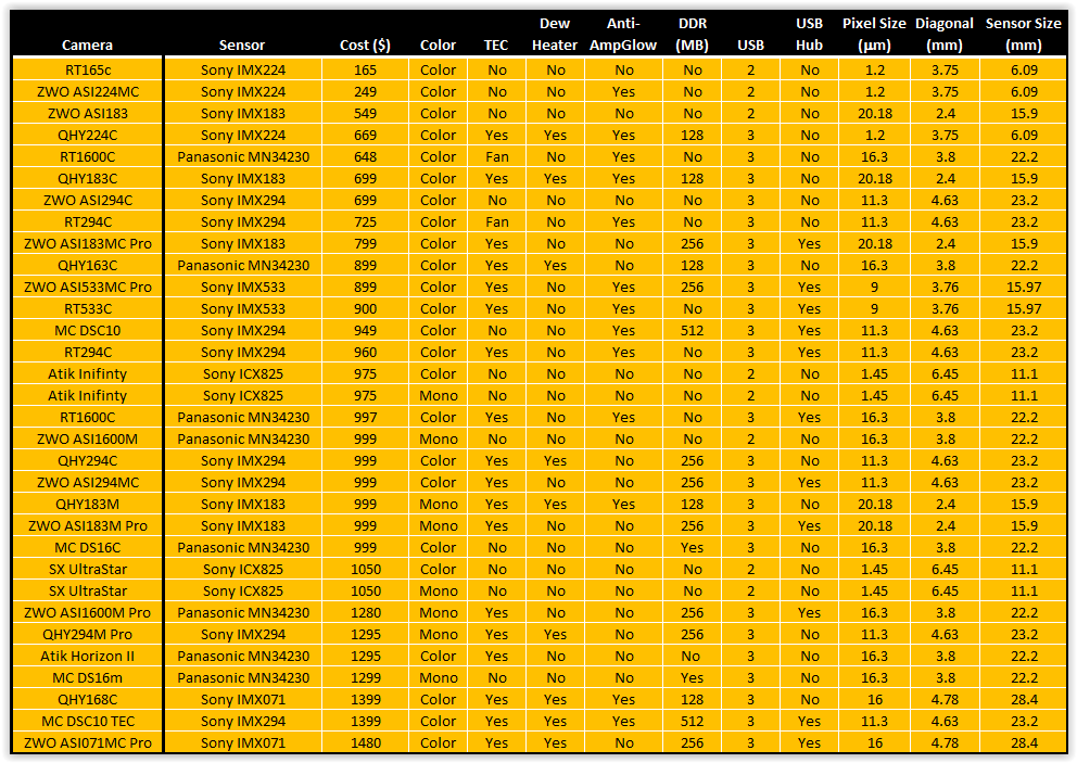 When choosing among cameras with the same sensor but from different manufacturers here are some additional things to look for: 1. DDR Memory: Built in DDR memory comes in either 128MB or 256MB. Note that 1 MB is the same as 8Gb as some express the memory in Gb instead of MB. It takes 8 bits (b) to make 1 byte (B). This added memory prevents frames from being dropped when transferring the data from the camera to the computer due to the high pixel count of many cameras. It can have the added benefit of reducing amp-glow as discussed below. ZWO cameras typically uses 256MB as does Mallincam while QHY uses 128MB except in their highest end cameras. Rising Tech generally does not indicate whether or not any of their cameras have memory. 2. USB Hub: Typically, cameras with cooling come with a 2 port USB2.0 Hub which can be used to connect two other devices such as a filter wheel, focuser or guide camera. This simplifies cabling and reduces the number of cables which must hang from the telescope to a computer or a USB Hub below. ZWO, Rising Tech and Mallincam provide 2 port USB2.0 hubs on their cooled cameras but QHY does not. 3. Anti-Amp Glow: In addition to DDR memory, some cameras have additional methods to combat amp-glow which may include software and additional hardware tricks which they do not explain in any detail. QHY indicates Anti-Amp-Glow features on some of their cameras while Rising Tech and Mallincam indicate it on almost all of their cameras. ZWO claims Anti-Amp-Glow for their ASI224MC and on their newest full frame camera the ASI240MC Pro. 4. Anti-Dew: Cooled cameras will often cause water condensation on the sensor window which may even ice up completely bringing a viewing session to a grinding halt until the camera is warmed. All cameras come with a sealed window using a gasket to keep water vapor outside the sensor. QHY and Mallincam add a thin heater on the chamber window which keeps water from condensing on the window. QHY cameras and the Atik Horizon II have a removable and re-chargeable silica gel pack to absorb any water vapor inside the sensor chamber which must be removed and baked from time to time to remain absorbent. Mallincam vaccum seals the chamber on some of its cameras. Rising Tech does not indicate the presence of a heater. ZWO seems to only have the heater on its latest designs like the ASI240MC Pro, but does does offer an after market heater kit which can be easily attached to the camera window although the power connection is not integrated into the camera itself. 5. Fan: A few of the lower cost Rising Tech cameras use a fan instead of a TEC for cooling which will not produce the same low temperature noise reduction as a TEC. Some cameras with TEC also have a fan to assist with heat dissipation. 6. Accessories: Additional accessories vary greatly. ZWO includes USB cables for both the camera and the Hub (if present), as many as a half-dozen adapters/spacers which are helpful in setting the correct camera spacing. They also supply a camera cover and a soft carrying bag. Rising Tech includes a 1.25" adatper, one 2m USB3.0 cable, and a 2m guider cable with its non cooled cameras. With its cooled cameras Rising Tech supplies 1.25 and 2" adapters, a 1.5m USB3.0 cable, a power supply for the cooler and a hard plastic carrying case. Similarly Mallincam provides a 2" adapter, one 15ft USB3.0 cable, and a guider cable with its non-cooled cameras and adds a power supply for the cooler and a hard plastic carrying case for its cooled cameras. QHY supplies their cameras with a 2" adapter, 1.5m USB3.0 cable, power and guider cables, a car power adapter, a desiccant tube and desiccant. 7. Software: Camera control and live stacking software has become very common for EAA since Robin Glover introduced SharpCap in 2010. SharpCap works natively with both ZWO , QHY and Starlight Xpress cameras and will work with other cameras using an ASCOM driver. The free version of SharpCap has camera control and live stacking capability. ZWO also has their own proprietary software called AstroLive which only works with their cameras. Rising Tech cameras come with Rising Sky software and Mallincam cameras with Mallincamsky. Atik cameras have their proprietary softwaren called Infinity which is considered one of the easiest and most intuitive software applications to learn because it does not have all of extra features not absolutely needed for EAA as does SharpCap. Starlight Xpress's software is called Starlight Live. While all of these do live stacking and on the fly processing, SharpCap is arguably the most complete package, especially if one uses the subscription version which includes plate solving, polar alignment and many other useful functions which are not necessary for EAA but make the process of setting up, aligning, focusing, etc. much easier. But it can have a steep learning curve. Certainly camera manufacturers try to distinguish themselves from their competitors so there are other differences among them including the use of AR coatings on chamber windows, DDR3 vs DDR2 memory, global vs rolling shutters, etc. Check competing manufacturer's sites for these additional details. We will only consider cameras under $1500 even though there are a multitude of cameras beyond that price range because cameras need not cost so much to bee fully sufficient to meet every EAA need. More expensive cameras can be considered if one anticipates using a single camera for EAA and astrophotography. The table above lists the wide assortment of cameras within this price range from ZWO, QHY, RisingCam, Mallincam, Atik and Starlight Xpress (SX). For those in Europe, Altair Astro in the UK has a wide assortment of the same cameras. It is widely understood that cameras from RisingTech, Altair Astro and Mallincam originate from the camera manufacturer ToupTek in China. (Note that cameras from RisingCam are commonly referred on the astronomy forums as RisingTech as I think this was their original name). These re-branded cameras are able to select different options from the original equipment manufacturer and may even provide different specifications to distinguish their cameras from their competitors. For instance, Mallincam specifies ZWO, QHY, Atk and SX all manufacture their own cameras but, as mentioned above, choose from the same supply of sensors as everyone else. Cameras using the Sony IMX224MC color sensor were the first CMOS cameras used for EAA. Since the sensor only has a 6mm diagonal and 1.2MP, cameras with the IMX224 are now more often used as planetary cameras but can still be a great entry level EAA camera due to their low price. Because of the very small diagonal of this sensor the FOV will be very narrow for any telescope at a focal length of 1000mm or longer. Therefore it is common to use a focal reducer to get closer to 500mm focal length which will provide a FOV close to 0.5deg. Otherwise, it can be difficult to find DSOs unless you are using a plate solving software. Cameras with the IMX224 sensor can be obtained from Rising Tech on AliExpress for $165 or from ZWO from most astronomy retailers for $199. Both are uncooled cameras with a small form factor body which will not have a problem working at the zenith in an Alt-Az mount like the Celestron Nexstar. QHY offers a cooled version with anti-amp glow and internal memory for $669 but it will not work near the zenith on mounts like the Nexstar because of its large body. Soon after the IMX224 cameras were introduced, the Panasonic MN34230 sensor with 16MP became available in cameras from a number of different manufacturers. These immediately became popular for EAA due to their larger sensors and reasonable prices. Cameras with the Panasonic sensor come in cooled, uncooled, color and mono versions. Cameras with mono sensors are always significantly more expensive than their color cousins. Rising Tech offers an uncooled color camera with the Panasonic IMX1600 chip for $648 and a cooled version for $997 while QHY offers its cooled color version for $899. ZWO discontinued their color version of this camera a few years back and now only offers the mono cameras in uncooled and cooled versions for $999 and $1280, respectively while Risking Tech's uncooled mono camera sells for $990. Mallincam's cooled color camera is available for $999. More recently, the Sony IMX294 sensor with 11.3MP started showing up in cameras from ZWO, QHY, Rising Tech and Mallincam. With a similar sensor size as the Panasonic MN34230, the Sony IMX294 provides a much deeper well depth, slightly larger pixels for greater sensitivity and 14 bits instead of 12 bits ADC. ZWO offers its ASI294MC uncooled color camera for $699, or its ASI294MC Pro cooled color camera for $999. QHY has a color cooled version, QHY294c, for $999. Rising Tech has an uncooled color version for $725 and a cooled color version for $960. Mallincam's DSC10 is an uncooled version for $949. 1" format sensors with ~16mm diagonals can be found in the 20MP IMX183 and the 9MP IMX533 Sony sensors. The least expensive camera in the 1" format is the uncooled ZWO ASI183 for $499. The QHY183c and the ZWO ASI183MC Pro cameras are both cooled color cameras and retail for $699 and $799, respectively. Cooled mono versions are $999 from both QHY and ZWO. The IMX533 sensor can be found in the cooled ZWO ASI533MC and Rising Tech 533c for $799 and $900, respectively. Just under $1000, Atik offers their Infinity camera with its signature rectangular shape and Sony ICX825 CCD with 1.2Mp on an 11.2mm diagonal. When first introduced about 5 years ago the Infinity was well received because of its performance and its Infinity live stacking software which is regarded as one of the easiest to master. But at $975 I believe it is now over priced given the fact that one can obtain a much larger sensor with cooling and internal memory for about the same price. If you have your heart set on one of these, look for a used camera for ~$450 on the Cloudy Nights classifieds. I have the same thought on the SX Ultrastar also with the ICX825 which sells for $1050. The camera table above lists 9 cameras above $1000, 4 of which are with mono sensors which always sell for much more than their color cousins. Unless you want to do mono EAA for the higher sensitivity, or want to use narrow band Ha or OIII filters to bring out specific details in nebulae, these are overkill for EAA. The QHY and ZWO cameras with the Sony IMX071 sensor are listed here because these have an APS-C format sensor with the largest diagonal at 28.4mm of all the cameras listed here. This would be a good camera if one wants to do both EAA and traditional astrophotography, but with such a large sensor expect to deal with significant vignetting. Summary
Clearly there are many possibilities when it comes to cameras for EAA. With so many choices it can be challenging to decide which camera is best suited to ones' needs. A good approach may be the following. First decide your price range. When doing so, consider waiting to to buy something with a much larger sensor than the IMX224 like the IMX183 cameras from ZWO or QHY rather than rushing into one of the low end cameras with the idea of buying a better camera later. While the IMX224 cameras are a great choice for someone on a tight budget, cameras like those with the IMX183 or even the IMX294 are a better choice for the long run if you can eventually work it into your budget by waiting. Or, pick up a higher end camera on the used market to move up in features right away. Cameras are pretty robust so there is not a great deal of risk to buy used. In that case it is a good idea to ask for a recent 60sec dark frame to make sure that the camera does not have too many hot pixels. Cooling is nice to have and essential for astrophotography, but for the short exposures used in EAA exposures cooling is not absolutely necessary. This will keep the cost down. If you are planning to use an Alt-Az mount with the telescope centered on the mount a cooled camera will make it impossible to view objects around 80 to 90 degrees in altitude. A sensor in the 15mm to 23mm range gives a good FOV for large objects without having to be too aggressive with focal reducers. Color cameras add a satisfying dimension to real time viewing which mono cameras cannot. When you do purchase a camera make sure that you have the necessary spacers to place the sensor at the correct distance from the back of the telescope to get an image without artifacts. Screw on spacers are better than slide on spacers since they will have less flex, but both will work. You can look through more detailed summaries of most of the cameras discussed here on the Oceanside Photo & Telescope (OPT) or the High Point Scientific web sites. OPT and High Point Scientific links are Affiliate links from which I can earn a commission at no cost to you. If you would like to support my web site and its content please consider using my links when ordering products. |
Categories
All
Archives
January 2024
|
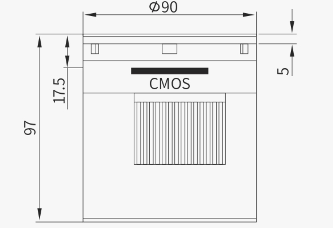
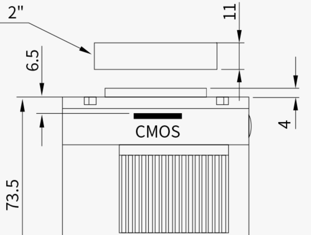
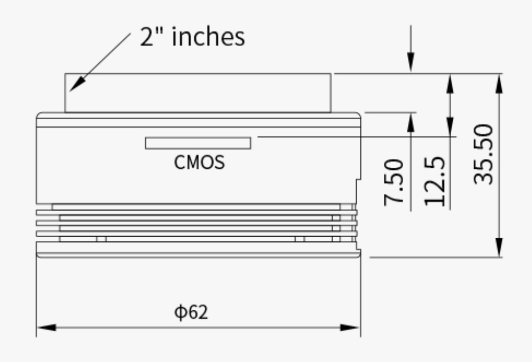

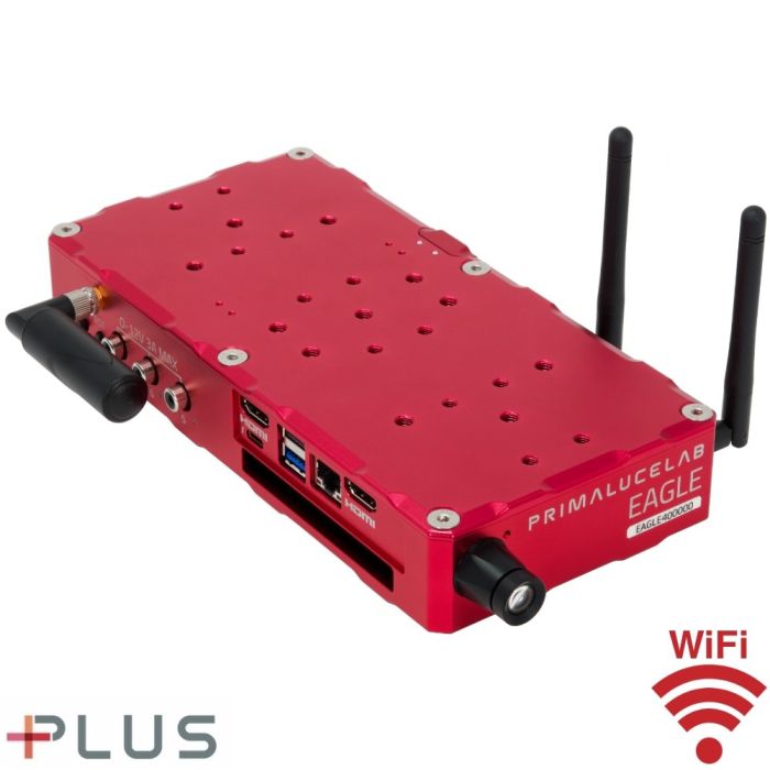
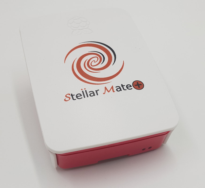
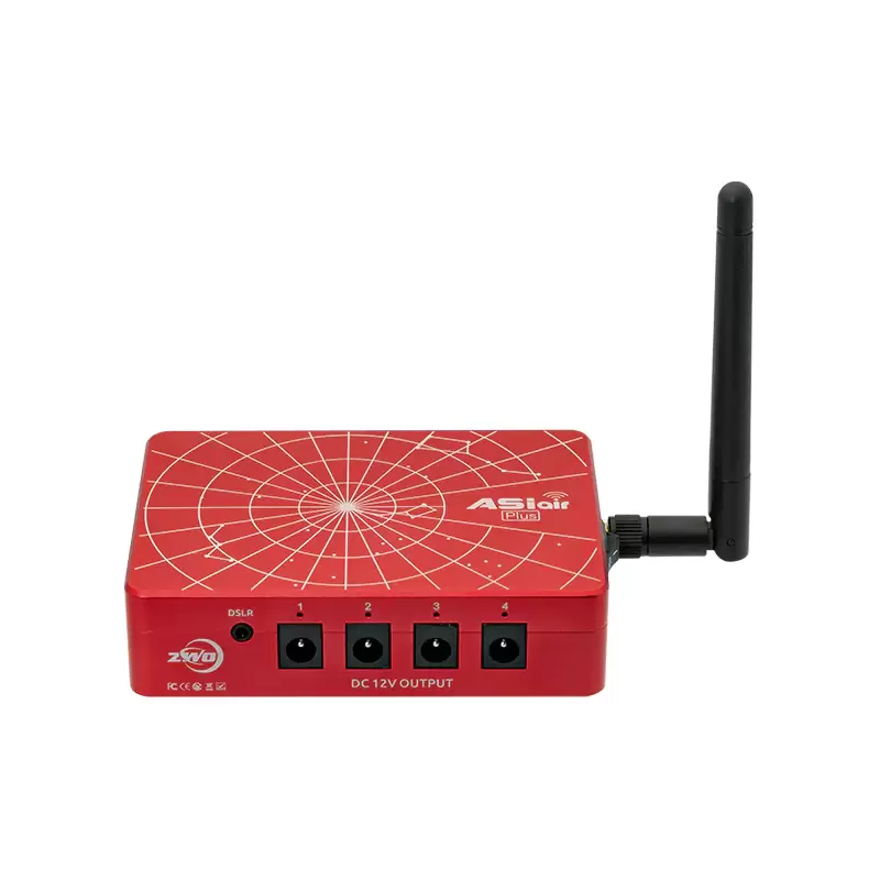
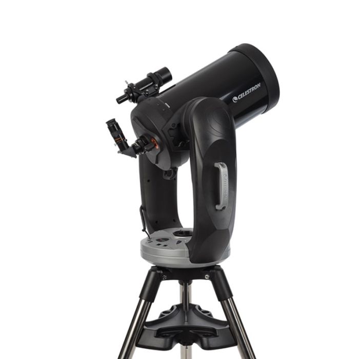
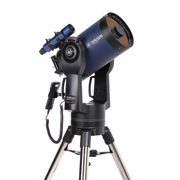
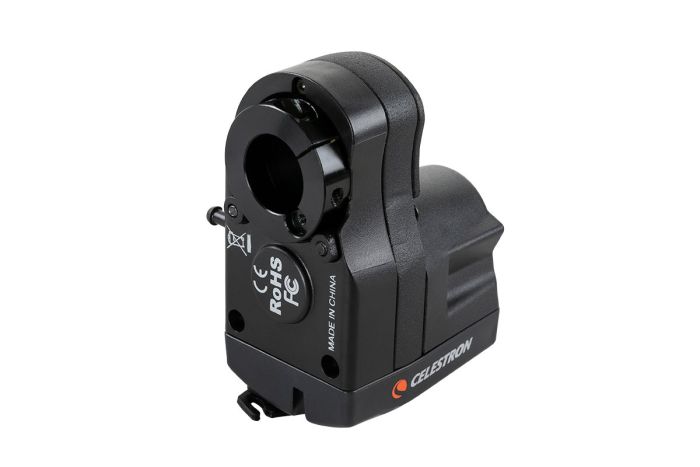
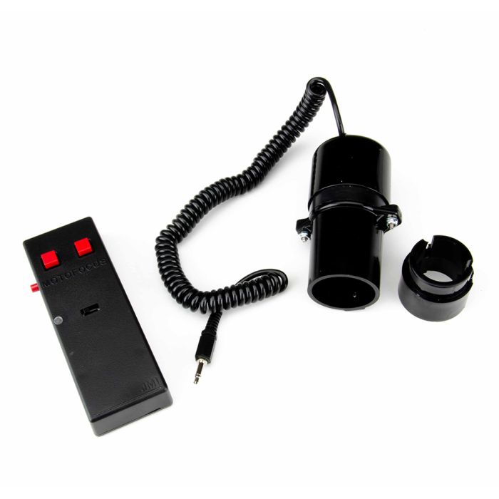
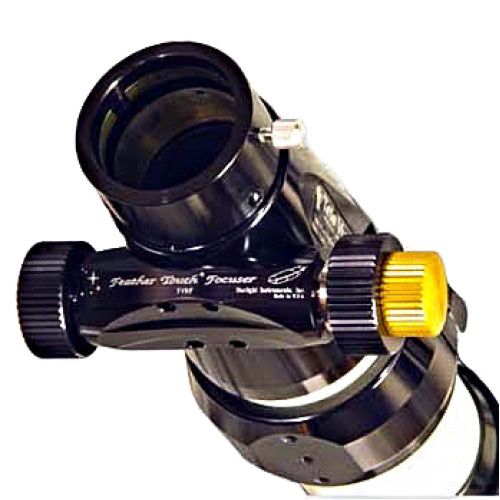
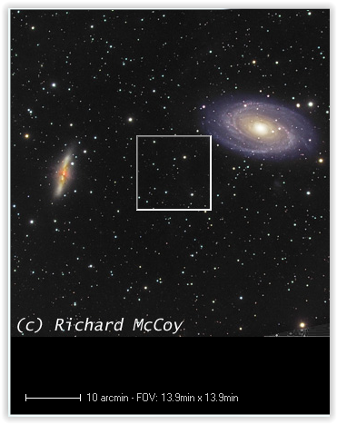
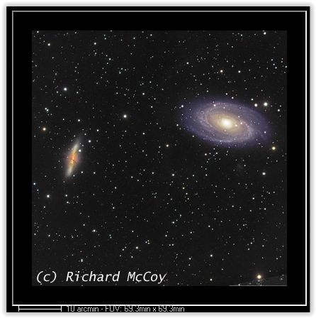
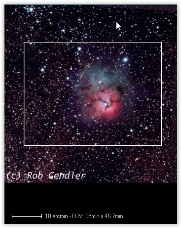


 RSS Feed